Présentation
Le but de ce projet est la réalisation d’une station capable d’effectuer certaines mesures (luminosité, température, humidité, humidité du sol) et d’envoyer ces données à une autre carte par ZigBee.
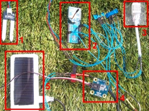
Voilà la carte de mesure :
composée de :
- Capteur de mesure d’humidité du sol de DF robot (http://www.dfrobot.com/index.php?route=product/product&product_id=599)
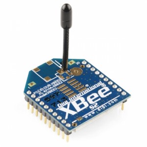
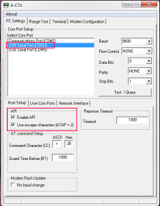
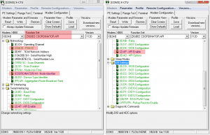
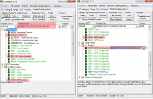
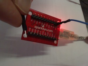
- Carte Arduino Fio + Module Xbee Serie 2 (en mode API/ZigBee)
- Capteur de température et humidité RHT03 de MaxDetect (http://www.sparkfun.com/products/10167)
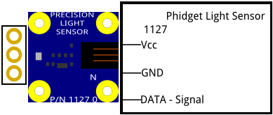
- Capteur de luminosité Phidgets 1127 (http://www.phidgets.com/products.php?product_id=1127_0) déjà utilise lors de précédents montage (lien vers article)
- Chargeur/batterie solaire pour téléphone portable relie à l’Arduino Fio
La carte de mesure communique avec une seconde carte autonome (je prévois de la relie a un Raspberry pi (http://www.raspberrypi.org/) dès que j’aurai réussi à m’en procurer un 😉
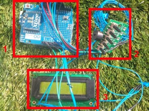
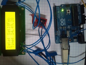
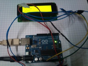
Voici la carte autonome :
composée de :
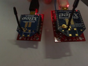
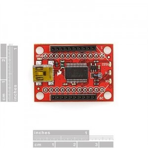
- Arduino Uno + “communication shield” avec un module Xbee Serie 2 en Mode Zigbee Routeur API
- Carte BP + Led pour interagir avec l’utilisateur
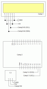
- Afficheur LCD I2C Barton déjà utilise dans des montages précédents
La carte Fille
Au boot la carte fille initialise certains éléments tels que la liaison série, Xbee dans la fonction d’init.
void setup()
 {
 // start serial port
 Serial.begin(9600);
 // start serial
 _Xbee.begin(9600);
 }
Ensuite le programme entre dans la boucle principale qui vérifie si un message est arrivé sur la liaison ZigBee
//Read if we received an inoming message
 _Xbee.readPacket();
 if (_Xbee.getResponse().isAvailable()) {
 // got something
Si un message est disponible alors il est stocke dans “_CmdReceived” (qui devient donc non nulle)
_CmdReceived = _ZbRxResp.getData(0);
Ensuite le programme va effectuer certains relevés (température, humidité, luminosité,…) en fonction de la valeur reçu :
if(_CmdReceived==1)
 {
 _DataToSend=analogRead(_InPinLedMeasure);
 }
 else if((_CmdReceived==2)||(_CmdReceived==3))
 {
 delay(50);
 DHT22_ERROR_t errorCode;
 Serial.print("Requesting data...");
 errorCode = _Dht22.readData();
 switch(errorCode)
 {
 case DHT_ERROR_NONE:
 if (_CmdReceived==2)
 {
 _DataToSend=_Dht22.getTemperatureCAsInt();
 }
 else if(_CmdReceived==3)
 {
 _DataToSend=_Dht22.getHumidityAsInt();
 }
 ...
 break;
 }
 }
 else if(_CmdReceived==4)
 {
 _DataToSend=analogRead(_InPinMoistureMeasure);
 }
Enfin, le process envoi la valeur mesure a la carte mère par ZigBee
aPayload[0] = _DataToSend & 0xff; //LSB
 Serial.print("Data0: 0x");
 Serial.println(aPayload[0], HEX);
 aPayload[1] = (_DataToSend >> 8) & 0xff; //MSB
 Serial.print("Data1: 0x");
 Serial.println(aPayload[1], HEX);
// Specify the address of the remote XBee (this is the SH + SL)
 XBeeAddress64 aAddr64 = XBeeAddress64(0x0013a200, 0x400a3e5e);
// Create a TX Request
 ZBTxRequest aZbTx = ZBTxRequest(aAddr64, aPayload, sizeof(aPayload));
// Send your request
 _Xbee.send(aZbTx);
Remarque importante sur la carte fille :
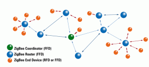
Pour la communication série avec le capteur de température DHT22 j’utilise une librairie disponible ICI. La communication ZigBee entre les modules Xbee se fait en Mode API (pour pouvoir utiliser un réseau MESH) avec la librairie disponible ICI. Je remercie d’ailleurs les DEV de ses librairies qui m’ont fait gagner un temps fou !
La carte Mère
La carte mère est composée d’un adruino UNO + shield ZigBee/Xbee et de 2 interfaces utilisateur : un écran LCD Barton (communication série) et une carte avec 5 BP et 5Leds.
L’écran LCD Barton est le même que dans mes montages précédant ou vous trouverez plus d’explication dessus et des exemples de codes. Les BP sont utilisés par l’utilisateur pour :
- Choisir la commande a envoyer ({“Moisture”, “Temp”, “Humidity”, “Light”};)
- Choisir le destinataire de la commande ({0x406b7b64, 0x400a3e5d};). Il s’agit en fait de l’adresse Xbee du module que l’on target.
- Envoyer la commande au destinataire.
Le choix de la commande et le choix du destinataire fonctionne de la même façon. Les différentes possibilités sont mise dans un ENUM et lie a deux autres tableau : un tableau pour le texte et un autre tableau pour le code de la commande.
enum Tcommand {
  Moisture=0,
  Temp,
  Humidity,
  Light,
  LastCommandIndex
};
const int _possibleCommand[] = {4, 2, 3, 1};
const String _possibleCommandTxt[] = {"Moisture", "Temp", "Humidity", "Light"};
Lors d’un appuie sur le bouton correspondant l’enum est incrémenté (et remis a zéro si on arrive au dernier) et le texte correspondant est affiche sur le LCD grâce a cette méthode :
void changeCommand()
{
  _Command=(Tcommand)(_Command+1);
  if (_Command>=LastCommandIndex)
  {
    _Command=(Tcommand)0;
  }
  lcd.clear();
  lcd.printstr("Command :");
  lcd.setCursor(1,0);
  lcd.printstr(_possibleCommandTxt[_Command]);
}
Une fois que la commande et le destinataire sont choisis il suffit d’envoyer le message avec un appuie sur un BP.
int aPayload=_possibleCommand[_Command];
    Serial.print("We are going to send a ZigBee message with Cmd : ");
    Serial.print(_Command);
    Serial.print(" which correspond to value : ");
    Serial.print(aPayload);
    Serial.print(" to this destination : ");
    Serial.print(_Receiver);
    Serial.print(" which correspond to value : ");
    Serial.println(_possibleReceiver[_Receiver]);
    sendZigBeeMsg(aPayload,_possibleReceiver[_Receiver]);
La commande est envoyée par ZigBee. Vous trouverez qq infos sur le ZigBee (pour les modules Xbee) dans mes articles précédents. Je vous rappelle que j’utilise une très bonne lib Xbee dispo ICI. Par rapport a mes premiers montage/code Zigbee j’ai ajouté la gestion du ACK qui fera sonner un buzzer si le message n’est pas bien envoyé/reçu.
void sendZigBeeMsg(unsigned int iPayLoad, unsigned long iAddrToTarget)
{
  Serial.println("We are going to send a ZigBee message");
  // Create an array for holding the data you want to send.
  uint8_t aPayload[1];
  // Fill it with the data
  aPayload[0] = iPayLoad;

  // Specify the address of the remote XBee (this is the SH + SL)
  XBeeAddress64 addr64 = XBeeAddress64(0x0013a200, iAddrToTarget);

  // Create a TX Request
  ZBTxRequest zbTx = ZBTxRequest(addr64, aPayload, sizeof(aPayload));

  // Send your request
  _Xbee.send(zbTx);
  Serial.println("Message Sent - Waiting for the ACK");

  if (_Xbee.readPacket(5000)) {
    Serial.println("We got a response to the message");

    // should be a znet tx status
    ZBTxStatusResponse aZbTxStatus = ZBTxStatusResponse();
    if (_Xbee.getResponse().getApiId() == ZB_TX_STATUS_RESPONSE) {
      _Xbee.getResponse().getZBTxStatusResponse(aZbTxStatus);

      // get the delivery status, the fifth byte
      if (aZbTxStatus.getDeliveryStatus() == SUCCESS) {
        Serial.println("The Trx was OK");
      }
      else {
        Serial.println("Warning : The Trx was KO");
      }
    }
    else{
      Serial.print("It was not a Trx status. ApiId:");
      Serial.println(_Xbee.getResponse().getApiId());
    }
  }
  else {
    Serial.println("Warning : This should never happen");
    flashPin(_OutPinBuz1, 1, 250);
  }
}
La carte mère vérifie également si une donnée a été reçue d’une carte fille (une réponse à une commande envoyée) et l’affiche sur le LCD.
if (_Xbee.getResponse().isAvailable()) {
    // got something
    Serial.println("We have something on the serial");
    Serial.print("ApiId: 0x");
    Serial.println(_Xbee.getResponse().getApiId(), HEX);

    if (_Xbee.getResponse().getApiId() == ZB_RX_RESPONSE) {
      Serial.println("This is a ZB response");

      // now fill our zb rx class
      _Xbee.getResponse().getZBRxResponse(_ZbRxResp);

      Serial.print("Data0: 0x");
      Serial.println(_ZbRxResp.getData(0), HEX);
      Serial.print("Data1: 0x");
      Serial.println(_ZbRxResp.getData(1), HEX);
      _ServoPosition=word(_ZbRxResp.getData(1),_ZbRxResp.getData(0));
      //_ServoPosition = int(_ZbRxResp.getData(0),_ZbRxResp.getData(1));
      updateDisplayedValue(_ServoPosition);

      if (_ZbRxResp.getOption() == ZB_PACKET_ACKNOWLEDGED) {
        Serial.println("This is a ZB ACK");
      }
    }
  }
La prochaine étape est d’ajouter la possibilité de piloter la carte mère grâce à un site WEB PHP et une liaison USB depuis mon serveur Linux (ou un Raspberry Pi) pour envoyer les commandes. Je prévois également d’ajouter un pilotage CPL pour commander l’ouverture de volets.

