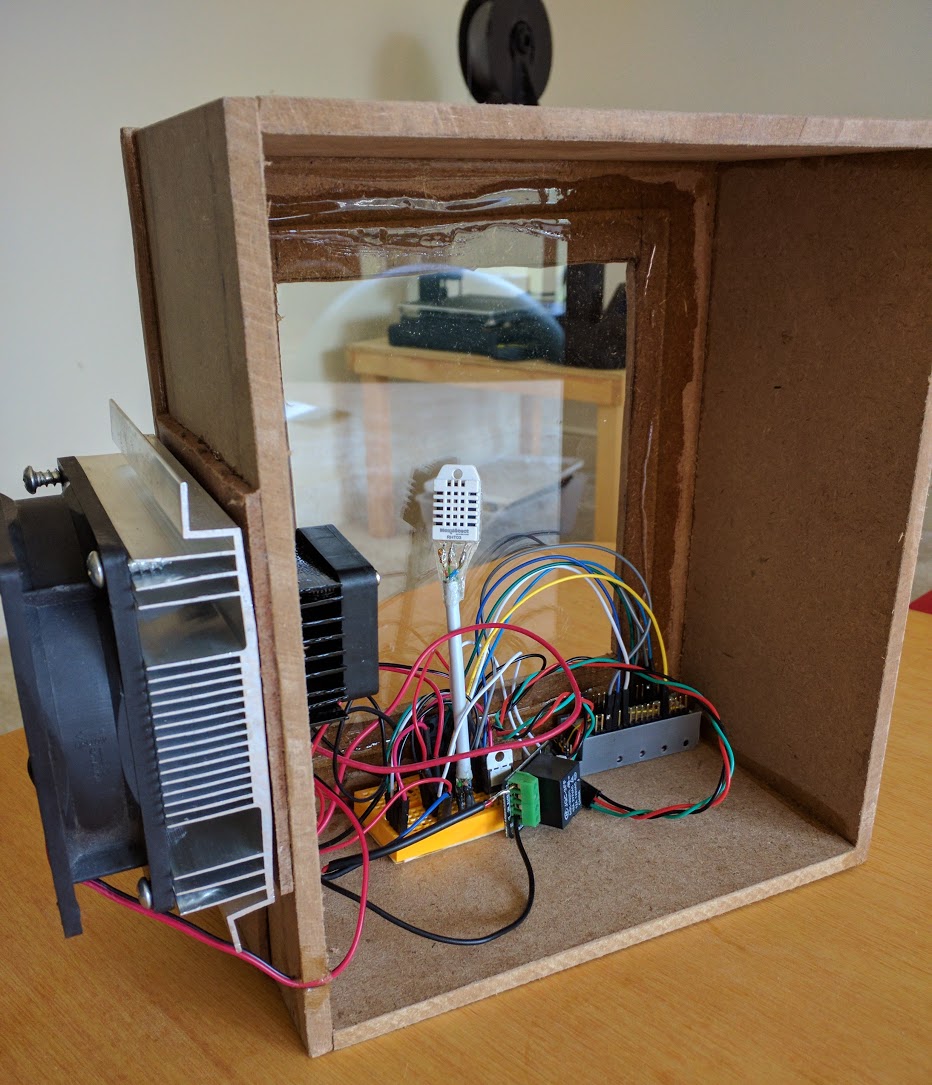
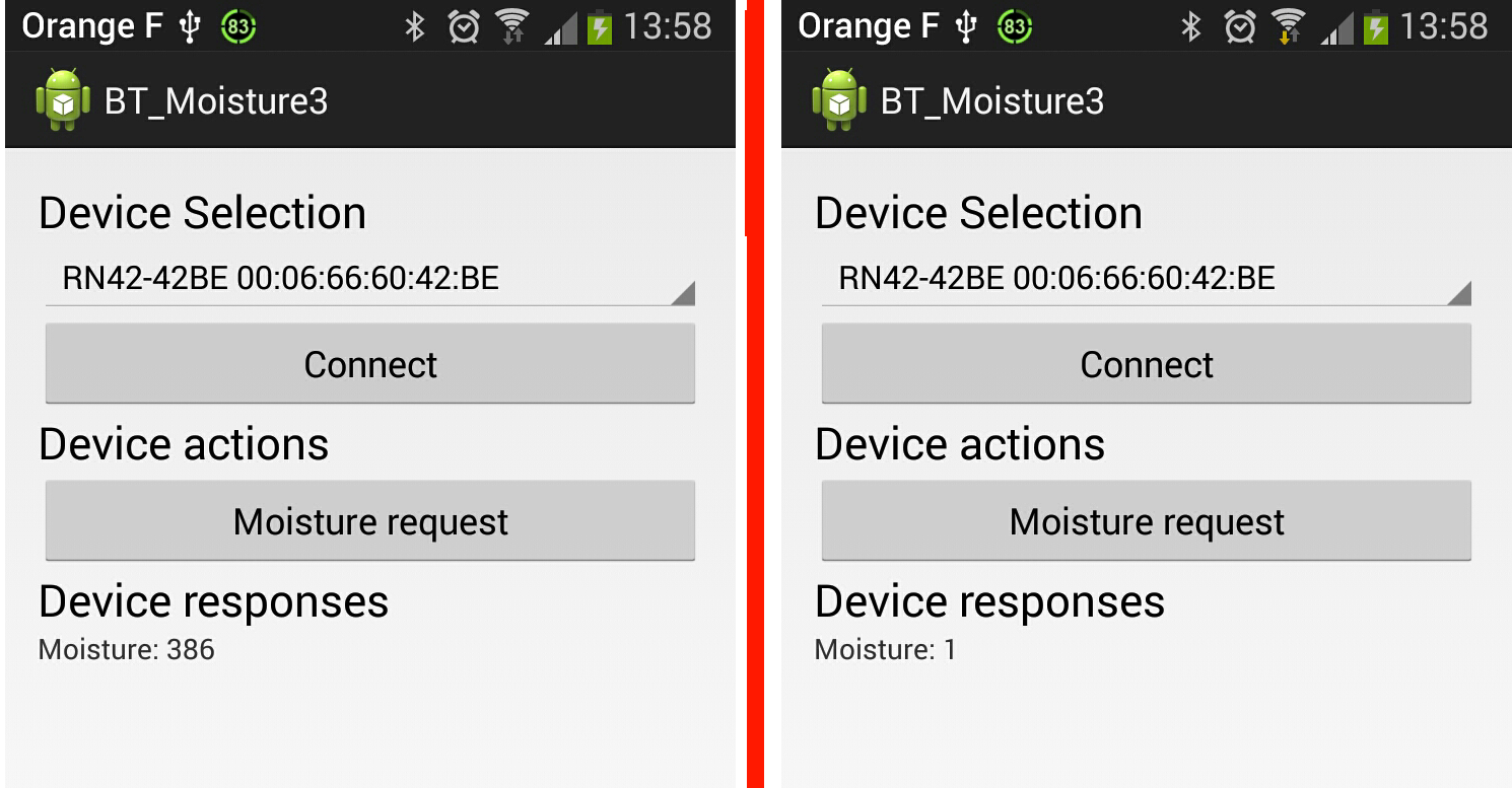
This article present how to use Bluetooth on Android device. The full project include Arduino Leonardo card and is detailed on this article : http://djynet.net/?p=639
First….some ressources to understand BT communication and BT handling on Android :
- https://learn.sparkfun.com/tutorials/using-the-bluesmirf/all
- https://learn.sparkfun.com/tutorials/bluetooth-basics/all
- http://developer.android.com/guide/topics/connectivity/bluetooth.html
Before starting….I thanks the guy who wrote the following article which help me a lot to understand android – Arduino BT links :
http://english.cxem.net/arduino/arduino5.php
I finish the DEV but it happen to be more complicated than I originaly think it would be… Especialy the “receive” part from Android which require ansynch tasks. Nevertheless I put lot of comments in the code so it should be easy to understand it.
The first things is to request BT use in the manifest :
<uses-permission android:name=”android.permission.BLUETOOTH” />
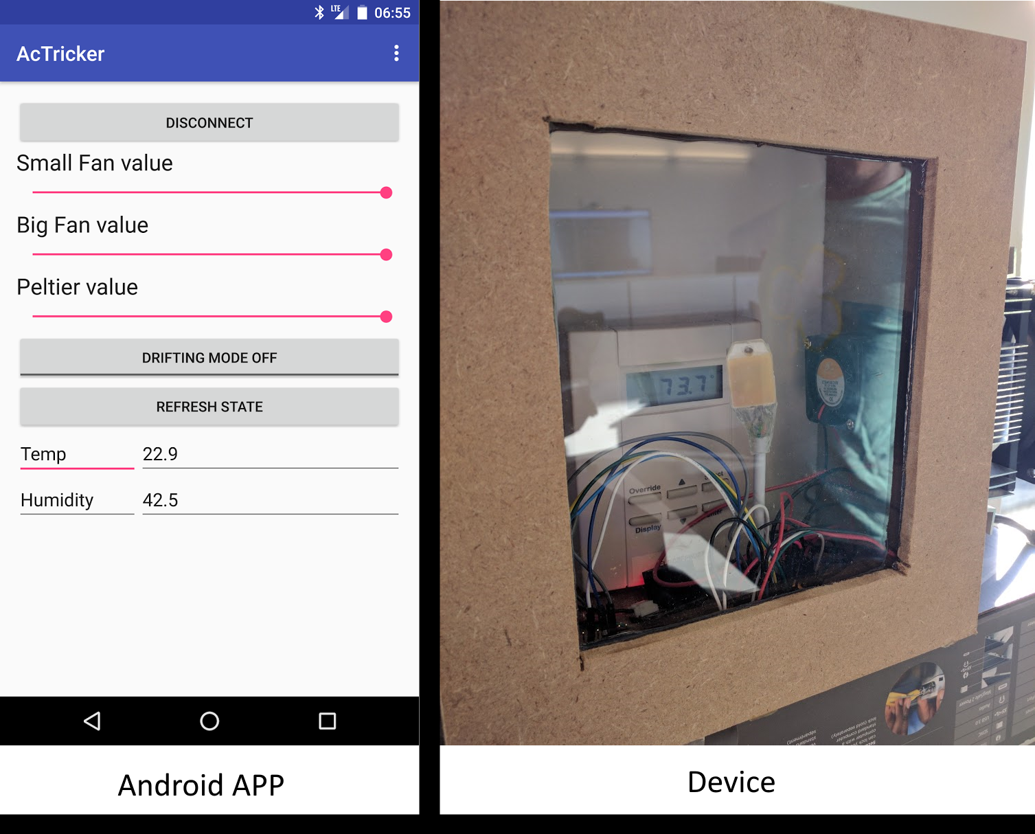
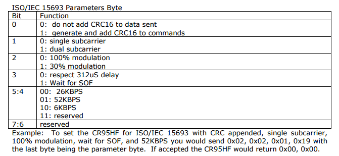
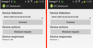
Then I created a simple layout with some button and textview to interact with the user

The first section hold the potential BT devices and allow to connect to the one selected. The second section is only 1 button “Moisture request” which will send the char ‘h’ to the arduino board. Last text view is used to display the Arduino response which is the moisture value in the earth.
The association button-callback is done in the xml view directly :
<Button
        android:layout_width="fill_parent"
        android:layout_height="wrap_content"
        android:id="@+id/connect"
        android:onClick="myClickHandler"
        android:text="@string/hello_world" />
At startup the program check if the phone as BT capability :
if (mBluetoothAdapter == null) {
            // Device does not support Bluetooth
            Log.w("MyActivity", "Device does not support Bluetooth");
            Toast.makeText(this.getParent(), "Go buy a more recent phone", Toast.LENGTH_LONG).show();
        }
and if the BT is not turn on it will request it to the OS (which will prompt the user) :
if (!mBluetoothAdapter.isEnabled()) {
                Log.i("MyActivity", "BT is not enabled. I request to start it");
                Intent enableBtIntent = new Intent(BluetoothAdapter.ACTION_REQUEST_ENABLE);
                startActivityForResult(enableBtIntent, 643);
            }
Another solution is to turn it on without asking kindly but it request more permission (in manifest).
Once the BT is ready the program will populate the UI with the list of paired devices :
BluetoothAdapter mBluetoothAdapter = BluetoothAdapter.getDefaultAdapter();
        Set<BluetoothDevice> pairedDevices = mBluetoothAdapter.getBondedDevices();
        // If there are paired devices
        if (pairedDevices.size() > 0) {

            //Fill the spinner on view with devices
            Spinner spinner = (Spinner) findViewById(R.id.spinner);
            // Create an empty ArrayAdapter
            ArrayAdapter <CharSequence> adapter = new ArrayAdapter <CharSequence> (this, android.R.layout.simple_spinner_item );
            // Specify the layout to use when the list of choices appears
            adapter.setDropDownViewResource(android.R.layout.simple_spinner_dropdown_item);
            // Apply the adapter to the spinner
            spinner.setAdapter(adapter);
            //Populate IT !!
            for (BluetoothDevice device : pairedDevices) {
                adapter.add(device.getName() + "\n" + device.getAddress());
            }
        }
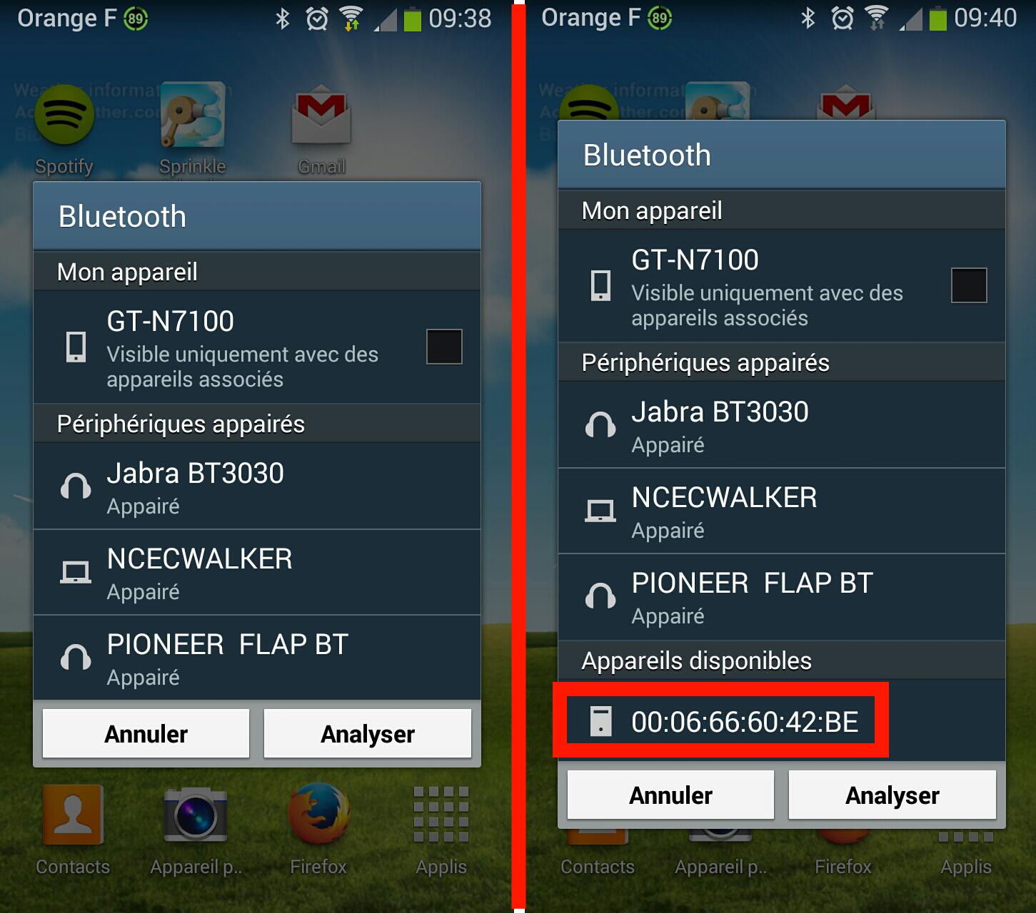
I didn’t handle the BT discovery here….which means that I already paired my Arduino with my phone. This operation could be done directly in android when you turn on the BT. It need to be done only 1 time and will ask you the code of the arduino BT module (1234).
Then….the user can select its module in the drop down menu (that we just populate in the previous function) and open a connection with it by pressing the “connect” button. It will call button callback :
public void myClickHandler(View v) {
        Log.i("MyActivity", "click button");
        connectMoisture();
    }
which call the real interesting process 🙂
protected void connectMoisture()
{
BluetoothAdapter mBluetoothAdapter = BluetoothAdapter.getDefaultAdapter();
Log.i("MyActivity", "We open the connection");
// I will use the standard SPP UUID - remember it is not link to our device on contrary of MAC address
UUID aSppUuid = UUID.fromString("00001101-0000-1000-8000-00805F9B34FB");
// The Arduino BT receiver address
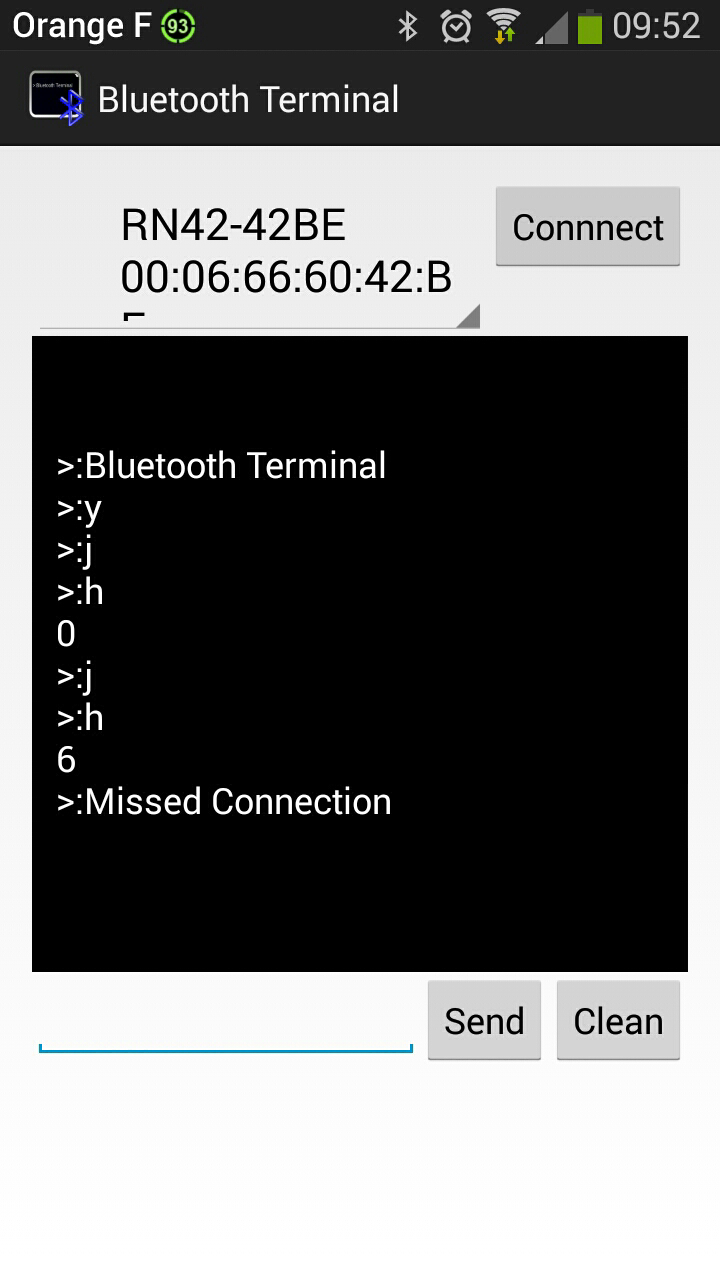
String aArduinoBtAddress = "00:06:66:60:42:BE";
try{
Log.i("MyActivity", "Going to retrieve the device");
BluetoothDevice aBtDevice = mBluetoothAdapter.getRemoteDevice(aArduinoBtAddress);
Log.i("MyActivity", "Device retrieved, creating socket now");
_blueToothSocket = aBtDevice.createRfcommSocketToServiceRecord(aSppUuid);
Log.i("MyActivity", "Socket created");
}catch(IOException createSocketException){
Log.e("MyActivity", "error1508"+ createSocketException.getMessage());
}
// Establish the connection. This will block until it connects.
Log.i("MyActivity", "Will try to connect to remote device");
try {
_blueToothSocket.connect();
Log.i("MyActivity", "Connection is done");
} catch (IOException e) {
Log.e("MyActivity", "error148"+ e.getMessage());
try {
Log.i("MyActivity", "Closing socket");
_blueToothSocket.close();
Log.i("MyActivity", "Socket closed");
} catch (IOException e2) {
Log.e("MyActivity", "another issue" + e2.getMessage());
}
}
// Step 3 create stream to talk with BT deice
try {
_streamOutgoing = _blueToothSocket.getOutputStream();
} catch (IOException e) {
Log.e("MyActivity", "another issue" + e.getMessage());
}
}
Now the program is connected to the device (the Ardunio BT board will probably have a LED which will reflect this new state). The user can now request the moisture value by clicking on the second button :
public void mySecondClickHandler(View v) {
        Log.i("MyActivity", "Sending h");
        //sendData("l");
        sendData("h");

    }
which call a sending routing with ‘h’ char :
protected void sendData(String message) {
        // start thread which handle input BT data before we send the request to Arduino.
        // With this design we know that we will be able to handle response
        ImplementsRunnable rc = new ImplementsRunnable();
        Thread t1 = new Thread(rc);
        t1.start();
        // The thread which is listening to input data from Arduino is now started
        // We can go to next step and send request to Arduino

        //Convert the String to send to byte
        byte[] msgBuffer = message.getBytes();
        Log.d("MyActivity", "About to send : " + message);

        try {
            _streamOutgoing.write(msgBuffer);
            //The next line is sending h char. I kept it as a debug test because I was worried Android will add extra char which will not be understand on Arduino side like end of line
            //_streamOutgoing.write('h');
        } catch (IOException e) {
            Log.e("MyActivity", "Error when trying to send data : " + e.getMessage());
        }
        //This is over. The Arduino response will be handle separately by another thread that we started before sending the request
    }
OK….So here I have to explain the first part where we start a dedicated thread. Before sending the request to Arduino Board we start a thread which will wait for incoming data on BT. It is the normal way to handle incoming message. The other part of the function is the data sending to arduino.
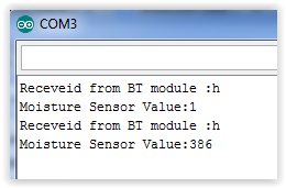
After this call the arduino received the char ‘h’ which trig a moisture detection and it will send back the moisture value to the BT module which will send it to the Android Phone.
As explained the reception is done in a dedicated thread. This is done by the following class which implement the “runable” interface :
class ImplementsRunnable implements Runnable {
        private InputStream _streamIncoming = null;

        public void run() {
            Log.d("MyActivity", "Thread run");

            //First we retrieve the input stream of the BT socket to be able to read incoming bytes
            try {
                _streamIncoming = _blueToothSocket.getInputStream();
                Log.i("MyActivity", "Input stream acquired");
            } catch (IOException e) {
                Log.e("MyActivity", "another issue" + e.getMessage());
            }

            //This single read works because I only wait for one message from Arduino but we should have a infinite loop here to catch everything arriving all the time
            try {
                //Not clean but we only receive a small message
                BufferedReader aMyBufferReader = new BufferedReader(new InputStreamReader(_streamIncoming));
                String aArduinoDataStr = "";
                aArduinoDataStr = aMyBufferReader.readLine();

                Log.i("MyActivity", "Received " + aArduinoDataStr );
                _ThreadMsgHandler.obtainMessage(31444, aArduinoDataStr).sendToTarget();     // Send to message queue Handler

            } catch (IOException e) {
                Log.e("MyActivity", "another issue" + e.getMessage());
            }
            Log.i("MyActivity", "Leaving thread run method " );
        }
    }
Once data are received by this thread they will be forwarded to the UI thread. This is done by the use of ‘Android handler’ in the UI thread :
_ThreadMsgHandler = new Handler(Looper.getMainLooper()) {
            //Will be called when new message arrive from other threads
            public void handleMessage(Message msg) {
                Log.d("MyActivity", "Handler is handling a message of type : " + msg.what);
                switch (msg.what) {
                    //Random ID .... should be the same as the one use when sending the msg from the thread
                    case 31444:
                        String aMyMoistureValue = (String) msg.obj;
                        // For now we only log it and toast it
                        Log.i("MyActivity", "Toasting moisture value : " + aMyMoistureValue);
                        Toast.makeText(MyActivity.this, aMyMoistureValue, Toast.LENGTH_LONG).show();
                        TextView aMyTextViewHandlingResponse = (TextView) findViewById(R.id.textView);
                        aMyTextViewHandlingResponse.setText("Moisture: " + aMyMoistureValue);
                        break;
                    //I think it should never occurs but just to be safe we log it
                    default:
                        Log.w("MyActivity", "Received an unknown message type : " + msg.what);
                }
            };
        };
Don’t forget…..this methods in on the UI thread ! We will come back to it after I finish explaining my runable class…..
The Data are send from the runable class to the UI thread with the handler :
_ThreadMsgHandler.obtainMessage(31444, aArduinoDataStr).sendToTarget(); // Send to message queue Handler
which is “catch” in the UI thread by the handler I just show before. The important point is the 31444 which has to be the same and act as an unique identifier. To finish the UI thread toast this value (debuging) and update the textview.
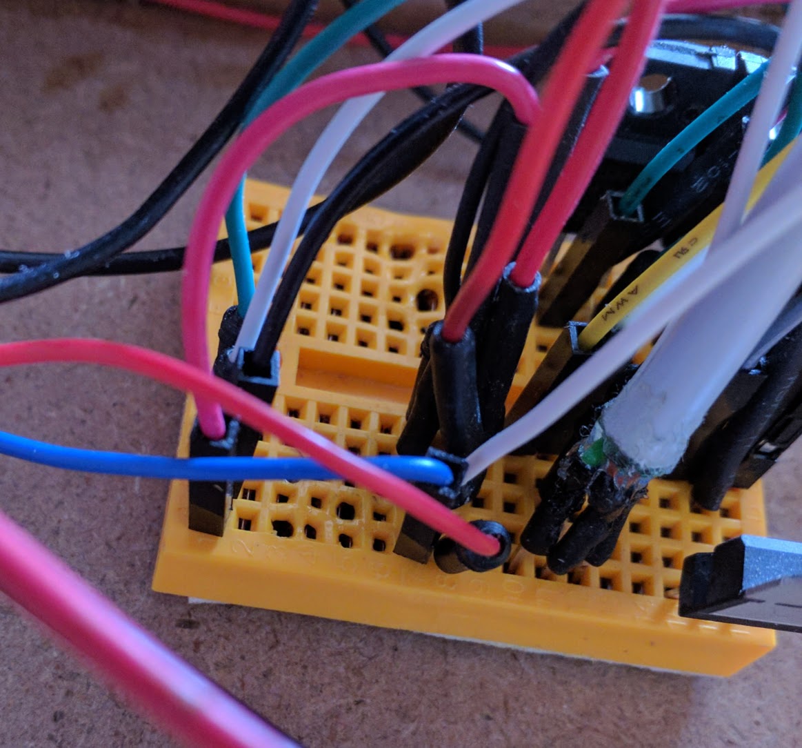
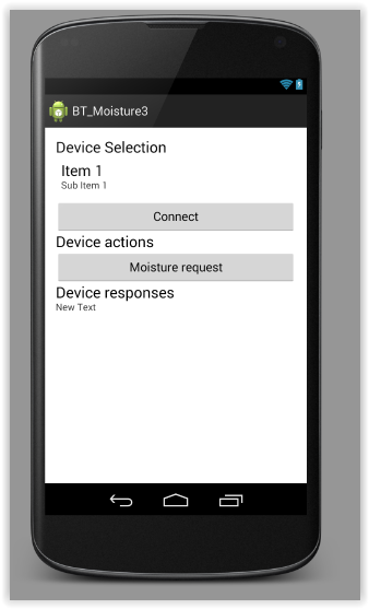
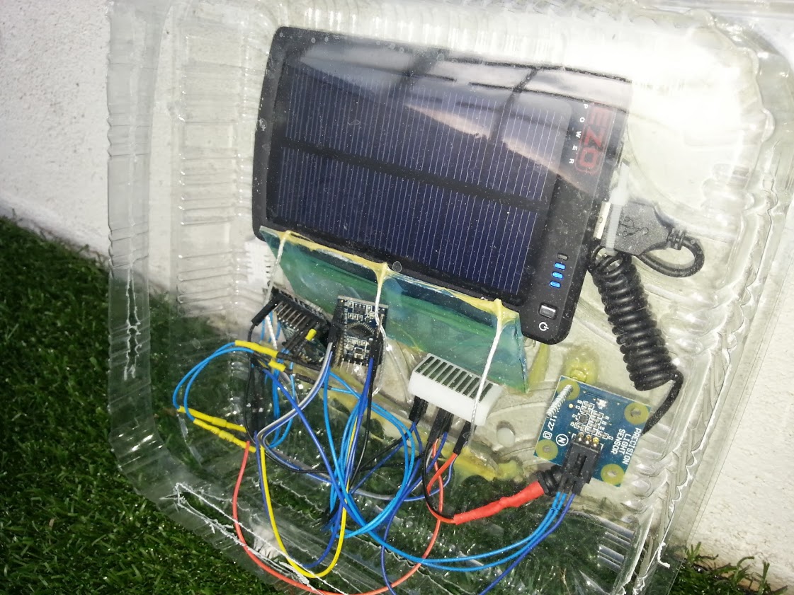
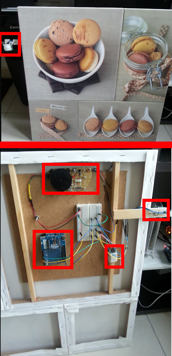
The results with the sensor in moist earth (or not) with the Arduino and Android output.
The whole code for the project (Android and Arduino) is on my bitbucket account here.