Mbed OS on Arduino Nano 33 BLE

Arduino release several new boards including the Nano 33 BLE which pick my interest due to the fact that it is based on the Nrf52480 chip ( https://www.nordicsemi.com/Products/Low-power-short-range-wireless/nRF52840) which should be compatible with Bluetoot MESH. I decided to give it a try…

This is the first board based on the Nrf52840 and thus there is no existing Arduino core for this board which means they would face some challenge to have Arduino running on it. They went for a smart solution by deciding to run Arduino Core on top of MBED OS to be able to use all the works already done by MBEDOS to integrate the nrf52840 chip. This is explain on their blog if you are curious: https://blog.arduino.cc/2019/07/31/why-we-chose-to-build-the-arduino-nano-33-ble-core-on-mbed-os/

That’s when I discover about MBEDOs ” Arm Mbed OS is a free, open-source embedded operating system designed specifically for the “things” in the Internet of Things. ” https://www.mbed.com/en/platform/mbed-os/ which seems promising especialy since it has a very complet Bluetooth stack Cordio (https://os.mbed.com/docs/mbed-cordio/19.02/introduction/index.html) which include Bluetooth MESH capability (https://community.arm.com/iot/b/blog/posts/bluetooth-mesh-with-bluetooth-5-and-cordio-radio-ip) which is not offer today by the Arduino Bluetooth library (https://github.com/arduino-libraries/ArduinoBLE/issues/22). That’s why i decided to give a try to program with MBEDos directly instead of Arduino. Nevertheless my first idea was to keep the arduino bootloader on the board so that I can program it WITHOUT any extra device and benefits from arduino bootloader.

Code

I used MBED studio to avoid dealing with the setup of a toolchain on windows: https://os.mbed.com/studio/

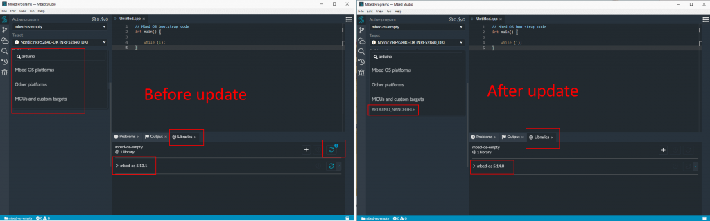
The only “difficulty” is to use a mbed version recent enough (>=5.14) to have the adruino nano 33 in the list of target.

I ve done a very simple program that will blink 3 times a LED on pin

#include "mbed.h"
#include "ble/BLE.h"

DigitalOut led1(p47);

// main() runs in its own thread in the OS
int main()
{
    //Pattern is 3 blink and wait 
    while (true) {
        // Turn led on
        led1 = 1;
        wait_ms(200);
        led1 = 0;
        wait_ms(200);
        led1 = 1;
        wait_ms(200);
        led1 = 0;
        wait_ms(200);
        led1 = 1;
        wait_ms(200);
        led1 = 0;
        wait_ms(3000);
    }
} 

Also in the folder of your project you should have a /mbed-os/targets/targets.json with the NANO33 definition.

I added 2 parameters “”OUTPUT_EXT”: “bin”” to generate a bin file instead of an hex file (the uploader use bin files)

The second change is “”mbed_app_start”: “0x10000″” so that the toolchain know my program will be located in memory at address 0x10000. This info is part of the arduino bootlaoder code and was explain to me here: https://github.com/arduino/ArduinoCore-nRF528x-mbedos/issues/19 The arduino bootloader will call the code at this address after it boot.

After you compile the code with MBED studio you will have the result binary here “C:\Users\charl\Mbed Programs\mbed-os-example-blinky\BUILD\ARDUINO_NANO33BLE\ARMC6” that can be uploaded to the board

upload

This part is tricky since my original goal is to use the arduino bootloader to upload my code to the board without any other tools. It took me some time to understand how to do it but hopefuly i got some help here https://github.com/arduino/ArduinoCore-nRF528x-mbedos/issues/19 and so i decided to use BOSSAC which is the same tools used by the arduino IDE. You can see it in the logs if you activate the extra logs in the IDE.

I re-use the bossac binary that is shipped with the arduino IDE and added an option to upload at address 0x10000. You need to press twice the reset button on the board to force the bootloader to run forever before starting the upload command.

C:\Users\charl\AppData\Local\Arduino15\packages\arduino\tools\bossac\1.9.1-arduino1> .\bossac.exe -d --port=COM5 -o 0x10000 -U -i -e -w 'C:\Users\charl\Mbed Programs\mbed-os-example-blinky\BUILD\ARDUINO_NANO33BLE\ARMC6\mbed-os-example-blinky.bin' -R                                                    Set binary mode                                                                                                                                         version()=Arduino Bootloader (SAM-BA extended) 2.0 [Arduino:IKXYZ]
 Connected at 921600 baud
 identifyChip()=nRF52840-QIAA
 write(addr=0,size=0x34)
 writeWord(addr=0x30,value=0x400)
 writeWord(addr=0x20,value=0)
 version()=Arduino Bootloader (SAM-BA extended) 2.0 [Arduino:IKXYZ]
 Device       : nRF52840-QIAA
 Version      : Arduino Bootloader (SAM-BA extended) 2.0 [Arduino:IKXYZ]
 Address      : 0x0
 Pages        : 256
 Page Size    : 4096 bytes
 Total Size   : 1024KB
 Planes       : 1
 Lock Regions : 0
 Locked       : none
 Security     : false
 Erase flash
 chipErase(addr=0x10000)
 Done in 0.003 seconds                                                                                                                                   Write 43884 bytes to flash (11 pages)                                                                                                                   [                              ] 0% (0/11 pages)write(addr=0x34,size=0x1000)                                                                            writeBuffer(scr_addr=0x34, dst_addr=0x10000, size=0x1000)                                                                                               [==                            ] 9% (1/11 pages)write(addr=0x34,size=0x1000)                                                                            writeBuffer(scr_addr=0x34, dst_addr=0x11000, size=0x1000)                                                                                               [=====                         ] 18% (2/11 pages)write(addr=0x34,size=0x1000)                                                                           writeBuffer(scr_addr=0x34, dst_addr=0x12000, size=0x1000)                                                                                               [========                      ] 27% (3/11 pages)write(addr=0x34,size=0x1000)                                                                           writeBuffer(scr_addr=0x34, dst_addr=0x13000, size=0x1000)                                                                                               [==========                    ] 36% (4/11 pages)write(addr=0x34,size=0x1000)                                                                           writeBuffer(scr_addr=0x34, dst_addr=0x14000, size=0x1000)                                                                                               [=============                 ] 45% (5/11 pages)write(addr=0x34,size=0x1000)                                                                           writeBuffer(scr_addr=0x34, dst_addr=0x15000, size=0x1000)                                                                                               [================              ] 54% (6/11 pages)write(addr=0x34,size=0x1000)                                                                           writeBuffer(scr_addr=0x34, dst_addr=0x16000, size=0x1000)                                                                                               [===================           ] 63% (7/11 pages)write(addr=0x34,size=0x1000)                                                                           writeBuffer(scr_addr=0x34, dst_addr=0x17000, size=0x1000)                                                                                               [=====================         ] 72% (8/11 pages)write(addr=0x34,size=0x1000)                                                                           writeBuffer(scr_addr=0x34, dst_addr=0x18000, size=0x1000)                                                                                               [========================      ] 81% (9/11 pages)write(addr=0x34,size=0x1000)                                                                           writeBuffer(scr_addr=0x34, dst_addr=0x19000, size=0x1000)                                                                                               [===========================   ] 90% (10/11 pages)write(addr=0x34,size=0x1000)                                                                          writeBuffer(scr_addr=0x34, dst_addr=0x1a000, size=0x1000)                                                                                               [==============================] 100% (11/11 pages)                                                                                                     Done in 2.076 seconds                                                                                                                                   reset()                                                                                                                                                 PS C:\Users\charl\AppData\Local\Arduino15\packages\arduino\tools\bossac\1.9.1-arduino1>

Seems to be working… nevertheless the LED do not blink 🙁

In the meantime I bought a programmer for the chip since the manufacturer has a “education/hobbyist” version for only 20$… https://www.segger.com/products/debug-probes/j-link/models/j-link-edu-mini/ I was not aware that i could had a official programmer for such low price….which made my original idea to reuse the Arduino bootloader to upload to avoid buying one useless…

Now that I have my hand on a programmer i decided to try to understand why my program was not running….is it my code or the upload failed or something else. I modify my code to remove the offset and start at address 0x0 and I upload it directly on the chip and the LED start blinking. The code is thus good and the issue seems located in the upload process… I decided to do another test and put back my offset 0x10000 in my program, erase the board, upload the Arduino bootloader in the board, and finally upload my program at address 0x10000 but not with BOSSAC but using the J-Link tool. The LED start blinking !

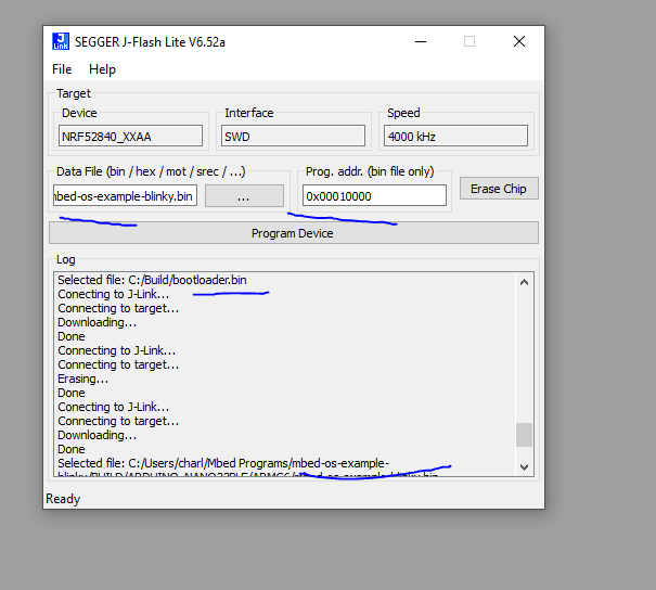
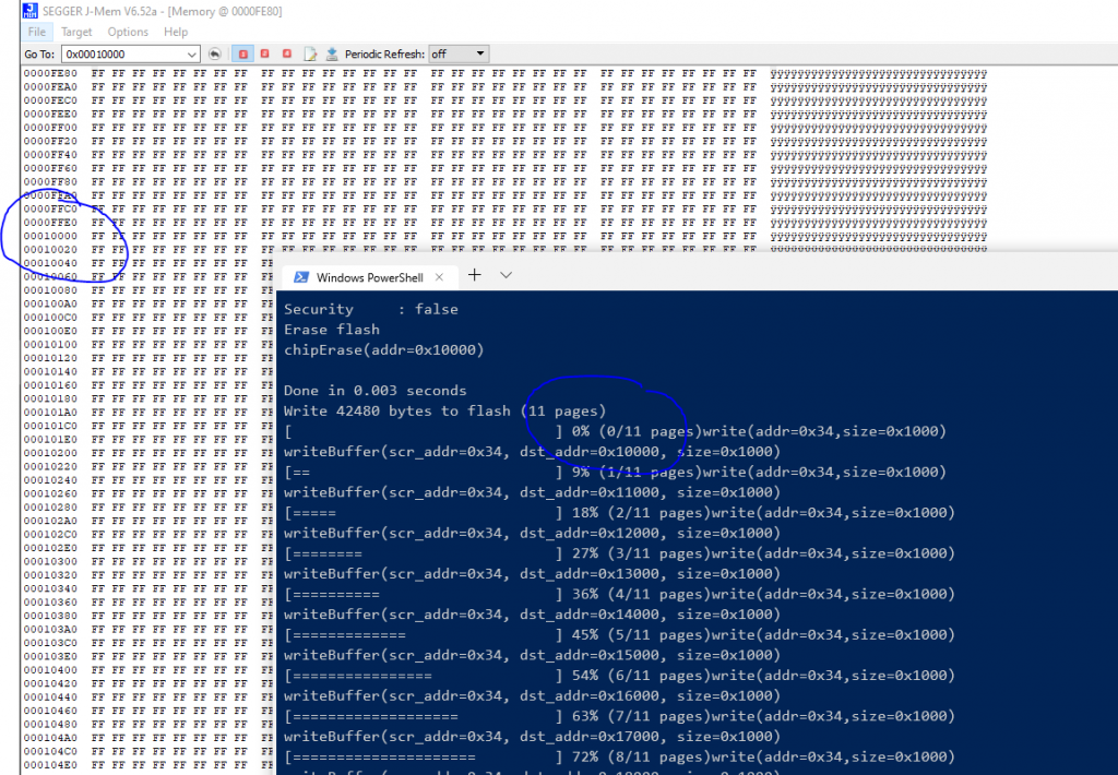
I compare the memory at address 0x10000 for both cases. First the test where i upload with BOSSAC at address 0x10000 and my program do not works

and when I upload with J-Link

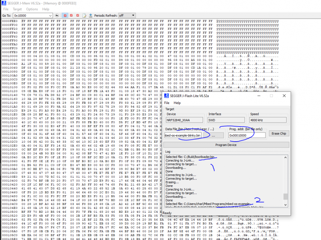
It seems the upload with BOSSAC do not works which seems to confirms what i thought.

Conclusion

I stop here since I now have a programmer to directly program the chip and so I can move on with my Bluetooth MESH tests.

Thx to https://github.com/facchinm for helping me understand more about Arduino bootloader and Thx to https://www.segger.com/ for selling a powerful programmer for hobbyist at a very reasonable price.

If you want to try MBED OS you should take a board compatible offering a DAP-Link for USB upload “Arm Mbed DAPLink is an open-source software project that enables programming and debugging application software on running on Arm Cortex CPUs. Commonly referred to as interface firmware, DAPLink runs on a secondary MCU that is attached to the SWD or JTAG port of the application MCU. This configuration is found on nearly all development boards. It creates a bridge between your development computer and the CPU debug access port. DAPLink enables developers with drag-and-drop programming, a serial port and CMSIS-DAP based debugging.” I would suggest this one for the Nrf52840 chip >> https://os.mbed.com/platforms/Nordic-nRF52840-DK/

DEFCON scale

Let’s start with an explanation of what is the DEFCON scale from https://en.wikipedia.org/wiki/DEFCON:

The DEFCON system was developed by the Joint Chiefs of Staff (JCS) and unified and specified combatant commands.[2] It prescribes five graduated levels of readiness (or states of alert) for the U.S. military. It increases in severity from DEFCON 5 (least severe) to DEFCON 1 (most severe) to match varying military situations.

https://en.wikipedia.org/wiki/DEFCON

and a picture of the final result to better understand how it look like

Hardware

The scale is made in wood with 9 LEDs behind each level/number

The logic of the scale comes from an arduino Micro with a BLE sparkfun BLE module “SparkFun Bluetooth Mate Silver – https://www.sparkfun.com/products/12576 ” (which is not used for now). The Arduino is powered by 9V regulated from the 12V main power (used for LED). Each number back light is control by a MOSFET (P30N06LE) driven by the Arduino. There are also 2 buttons for tests to increase/decrease the level.

Software

Arduino

The arduino micro communicate with a computer using USB to receive the level it should set on the scale. It will do that buy driving 5 MOSFET to light the proper panel. It also listen to press on 2 buttons to raise/decrease the level (for test purpose). The code is quite simple.

PC

The scale communicate with a computer to receive its level it should set. The level is computed from my work company issue tracking tool. The computation part code interface with some of my company API and is thus not part of the code…. You will have to code your logic in the python code in the function “getSeverity” which should return an integer between 5 (low level) and 1 (critical level) as the DEFCON standard 😉

The python part should be put in a crontab to regularly update the scale 😉

More picture of the project HERE and the code is HERE.

AcTricker

Im working in an openspace of 15 peoples and most of us are very cold. There is one thermostat for the whole openspace with the actual temperature display on it but it seems we cannot change the desired temperature… We complain several times to our management about it and after some time the responsible of the amenities comes and explains us the situation. The temperature is set by the landlord for the whole building and the sensor in our openspace is just to detect the temperature in our space to open air vent or not. In other word…there is nothing they can do about it, is it? 

This is the AcTricker! The solution to our problem 😉

It’s design to be put against the wall around the temperature sensor. It will create a cold micro climate around the sensor to trick it thinking that the office is cold and thus never start the AC in our openspace. It works with a Peltier device that generate cold inside the enclosure and Hot outside of the enclosure when a current is passing (I did not research how/why it is work but just use it as is).

The Peltier device is in sandwich with the hot face facing outside with a big heatsink/fan to dissipate the heat and the cold side facing in the enclosure with a smaller heatsink/fan. It is important to dissipate the heat/cold quickly otherwise the Peltier become inefficient. It would had been enough to stop here and the device would had been functional nevertheless I wanted to add more functionalities… 

The whole system is control with an android application with Bluetooth so people can check what is the simulated temperature inside the enclosure and act on it by stopping the Peltier device and fans. The brain of the whole system on the device side is an Arduino micro (small size). It is connected to a Bluetooth modem and a temperature/humidity sensor (DHT22/RHT03) for data exchange. There is also 2 MOSFET to control the fans and 1 static relay to control the Peltier device. 

The android application allows to retrieve Temperature and Humidity and control the fans and Peltier. The application design is very similar to the one I created for previous project (like this one) and use the BT of android to communicate with the device so i will not details again here. The Arduino side is also very similar to previous projects (same one than the app). Here is the system after it is plug (android screen capture on the right and device on the left) :

and the result 10 minutes after:

We reduce the temperature from 23 degrees Celsius to 19 degrees Celsius leading the AC to completely stop 😉

Code is on my bitbucket repo.

Improvement idea: Have the Arduino automatically stopping the Peltier/fan when the temperature inside is low enough to save power and reduce noise. 

Static Relay ??

I used a static relay for the Peltier device after burning 2 MOSFETs when trying to control the Peltier with them. The MOSFET were becoming very hot very quick and even damage the breadboard as you can see on the picture

At the beginning, I was not sure why the MOSFET was becoming so hot. I know that the Peltier device use lot of current (around 7A) but the MOSFET I used (P16NF06FP) should had been OK since it was able to handle load up to 11A (I use the TO-220FP package which is plastic package and thus dissipate less heat than the metal package):

After some research (and particularly this blog post) I think the explanation is that the MOSFET was not able to handle 11A with my configuration. I was driving the MOSFET from the Arduino with a voltage of 5V but the MOSFET require more voltage to be fully open. I was thus not able to use the full MOSFET capability due to a gate voltage too low. The impact of the gate voltage (Vgs) on the possible current output (Id) is also in the datasheet:

As you can see if we switch the Gate voltage from 5V to the recommended 10V the current we can drain grow from 7A to more than 28A.

This is why the MOSFET was become too hot and unusable. I should have bought a MOSFET design to be driven with a gate voltage more compatible with Arduino like the IRL540.

Raspberry Pi and HID Omnikey 5321 CLI USB

I recently come across a project where I needed to interact with some RFID tag. I wanted to retrieve the Unique ID of the each badge. I had absolutely no information on the badge except the string “HID iClass” written on it.

I start doing some research and found out that there are 2 big frequencies used in RFID: 125 kHz and 13.56 MHz. The iClass seems mainly based on the 13.56 MHz standard so I decided to go for a reader on this frequency.

Then I found out that there are several standard on this frequency. The most used are (in order) ISO 14443A, ISO 14443B, and ISO 15693. Nevertheless the iClass type includes several tag variations with all these standards. Finally I decided to buy the ADA fruit reader which handles both ISO 14443A and B: https://www.adafruit.com/products/364

I set it up with a Raspberry Pi 2 and was able to read the TAG send with the reader but sadly not the tag I wanted to read… Since I was unable to read my tag I guess they are using the third protocol: ISO 15693.

I look for some reader for the ISO 15693 but the choice is very limited (since it is not widely use). In the meantime I found a cheap HID reader on amazon (https://www.hidglobal.fr/products/readers/omnikey/5321-cli) which should be compatible with HID iClass card so I decided to buy it.

It works pretty well on Windows with their driver and software and gives me some useful information about my badge. It allowed me to confirm that it use the ISO 15693 standard:

It’s a good start nevertheless I wanted to use it on Raspberry Pi. I decided to do some research and found out that this type of RFID card reader is called “PCSC”:

PC/SC (short for “Personal Computer/Smart Card”) is a specification for smart-card integration into computing environments. (wikipedia)

Moreover there is a USB standard for such device: CCID.

CCID (chip card interface device) protocol is a USB protocol that allows a smartcard to be connected to a computer via a card reader using a standard USB interface (wikipedia)

Most USB-based readers are complying with a common USB-CCID specification and therefore are relying on the same driver (libccid under Linux) part of the MUSCLE project: https://pcsclite.alioth.debian.org/

There are plenty of soft related to RFID reading on Linux that I found during my research before choosing to try CCID. Here are my raw notes for future reference:

  • PCSC lite project
  • PCSC-tools
  • librfid
    • Seems dead
    • https://github.com/dpavlin/librfid
    • low-level RFID access library
    • This library intends to provide a reader and (as much as possible)
    • PICC / tag independent API for RFID applications
  • pcscd
  • libnfc
    • https://github.com/nfc-tools/libnfc
    • forum is dead
    • libnfc is the first libre low level NFC SDK and Programmers API
    • Platform independent Near Field Communication (NFC) library http://nfc-tools.org
    • libnfc seems to depend on libccid but it seems to depend on the hardware reader used :Note: If you want all libnfc hardware drivers, you will need to have libusb (library and headers) plus on *BSD and GNU/Linux systems, libpcsclite (library and headers).Because some dependencies (e.g. libusb and optional PCSC-Lite) are used
  • Opensc

I decided to go with the MUSCLE project available here: https://pcsclite.alioth.debian.org/ccid.html

After I installed the driver/daemon and the tools to interact with the reader I had trouble since the reader was not detected by pcscd. Luckily there is a section “Check reader’s compliance to CCID specification” on the pcsc page to know if the driver is supported. I follow it and send the repport to the main maintainer of pcsc driver: Ludovic Rousseau.

He confirms me that the driver was never tested with this driver and give me the instruction to try it :

Edit the file CCID/readers/supported_readers.txt and add the line:
0x076B:0x532A:5321 CLi USB
Then (re)install the CCID reader and try again to use the reader.
https://ludovicrousseau.blogspot.fr/2014/03/level-1-smart-card-support-on-gnulinux.html

I follow it and the reader gets detected by the daemon. Nevertheless the card is not detected so I provided more feedback/logs to Ludovic for debugging and sadly the result is that the reader cannot be supported:

The conclusion is that this reader is not CCID compliant. I am not surprised by this result.
You have to use the proprietary driver and no driver is provided for RaspberryPi.
If you are looking for a contactless reader have a look at https://pcsclite.alioth.debian.org/select_readers/?features=contactless

I will try to see if I can interact with the reader and libusb and also found a cheap open source ISO 15693 reader to continue this project.

Update 23JAN2017

I contact Omnikey to have support to use their reader for my project and they confirmed there is no driver on the Pi for it.

we don’t have any drivers for 5321 CLi on Raspberry Pi. Please have a look at OMNIKEY 5022 or OMNIKEY 5427 CK instead. The can be accessed through native ccidlib.

In the meantime I also bought another reader compatible with the ISO standard 15693: http://www.solutions-cubed.com/bm019/

I plug it with an Arduino Uno thanks to their blog article : http://blog.solutions-cubed.com/near-field-communication-nfc-with-the-arduino/

Nevertheless I was still unable to read the TAGS. I start doing deeper research and found that the ISO 15693 can have several settings and I do not know which one my iClass tags are using. I tried all the possible combinations that the BM019 handle:

Even with all the tests I made I’m still unable to read them. I dig deeper and found out that the BM019 module is built around the CR95HF ST chip. It seems that I’m not the only one trying to read Icalss with their IC and their support forum has several post explaining that it is not possible since iClass do not properly follow the ISO 15693 standard:

issue comes from Picopass which is not ISO 15693 complliant  ,
timing are not respected . 
We have already implemented a triccky commannd which allow us to support Picopass , a new version of CR95HF devevelopment softaware will be soon available including a dedicated window for PICOPASS .

After 3 readers and countless hours of attempt I’m still unable to read the iClass badges since they do not seems to implement any real standard.

Electric Train V3

Feel free to have a look on the V2 first:
http://djynet.net/?p=759

The biggest change is in the camera able to follow the phone orientation to update its angle. I also replace the front/rear sensors.

TrainV3

Camera tracking

I used the html5 API to detect the phone orientation:

if (window.DeviceOrientationEvent) {
  // Our browser supports DeviceOrientation
  window.addEventListener("deviceorientation", deviceOrientationListener);
} else {
  console.log("Sorry, your browser doesn't support Device Orientation");
}
function deviceOrientationListener(event) {
  var c = document.getElementById("myCanvas");
  var ctx = c.getContext("2d");

  ctx.clearRect(0, 0, c.width, c.height);
  ctx.fillStyle = "#FF7777";
  ctx.font = "14px Verdana";
  ctx.fillText("Alpha: " + Math.round(event.alpha), 10, 20);
  ctx.beginPath();
  ctx.moveTo(180, 75);
  ctx.lineTo(210, 75);
  ctx.arc(180, 75, 60, 0, event.alpha * Math.PI / 180);
  ctx.fill();

  ctx.fillStyle = "#FF6600";
  ctx.fillText("Beta: " + Math.round(event.beta), 10, 140);
  ctx.beginPath();
  ctx.fillRect(180, 150, event.beta, 90);

  ctx.fillStyle = "#FF0000";
  ctx.fillText("Gamma: " + Math.round(event.gamma), 10, 270);
  ctx.beginPath();
  ctx.fillRect(90, 340, 180, event.gamma);
  
  var aMsg = event.alpha.toString()+"_"+event.beta.toString()+"_"+event.gamma.toString();
  console.log("aMsg" + aMsg);
  doSend(aMsg);
}

Which send the 3 orientation information to the Tornado python server running on the Raspberry pi of the train. First I was doing JSON REST call to send the string containing the information but it was too slow to have the camera moving in real time. This was the perfect opportunity to use websocket for more real time communication.


function onOpen(evt) { 
        console.log("CONNECTED");
        doSend("Hi there!");
    }
    function onClose(evt) { 
        console.log("DISCONNECTED");
    }
    function onMessage(evt) { 
        console.log('message: ' + evt.data);
    }
    function onError(evt) { 
        writeToScreen('error' + evt.data);
    }
    function doSend(message) { 
        websocket.send(message);
    }
function testWebSocket() {
        websocket.onopen = function(evt) { onOpen(evt) };
        websocket.onclose = function(evt) { onClose(evt) };
        websocket.onmessage = function(evt) { onMessage(evt) };
        websocket.onerror = function(evt) { onError(evt) };
}
        

if (!'WebSocket' in window){
    console.log("Sorry, your browser doesn't support Websockets");
} else {
var wsUri = "ws://192.168.10.1:80/ws";
var websocket = new WebSocket(wsUri);
    testWebSocket();
}

Which is received on the server side and put in a variable (see the class Handler_WS) :

    def on_message(self, iMessage):
        """Methode call when the server receive a message"""
        logging.info('Receive incoming message:'+str(iMessage))
        #self.write_message("toto")
        self.aTrainRef._cellAngles=str(iMessage)

This variable is then read every 125ms by the “foo” function:

tornado.ioloop.PeriodicCallback(lambda: foo(aTrain), 125).start()

At the end the real method called is in charge of updating the turret position. The whole stuff is based on an existing framework called servoBlaster which will take care of driving the Servo.

def updateTurretFromScreenAngle(self):
        if (self._cellAngles!=""):
            #Update Gamma
            aGamma = self._cellAngles.split("_")[2]
            aGammaF = float(aGamma)
            aGammaI = int(aGammaF)
            aGammaisNegative = False
            if (aGammaI<0): aGammaI=(aGammaI*-1)-40 aGammaisNegative = True else: aGammaI=140-aGammaI if ((aGammaI>0)and(aGammaI<100)):
                self._turretHeight = 100 - aGammaI
                self.sendPos(ConstModule.CONST_SERVO_HEIGHT,self._turretHeight)
            #Update Alpha
            ...

Servo Blaster is library able to drive Servo on the Raspberry pi using software PWM. It is pretty hard to do since the Pi is not running a real-time OS. It relies on very low level interruption to ensure the timing needed to have a proper PWM are respected. You can have more info on it here:

https://github.com/richardghirst/PiBits/tree/master/ServoBlaster

It basically start a daemon (which I added in the crontab to be launch at boot time) on which you can interact with writing the desired position of each servo in /dev/servoblaster like:

echo 3=120 > /dev/servoblaster 

I also used servo blaster to send PWM info to the motor driver to change the train speed (since this functionality was broken when I moved from Arduino to Rapsberry Pi).

Contact sensors

I replace the old contact sensor by some new sensor able to detect an incoming obstacle before impact.

TrainSensorNew

They are still binary sensors that will turn high if they detect an obstacle but they have a wider range between 2 and 10 centimeters. This allows the train to detect incoming obstacle and stop before hitting it. The sensor is available on ADAfruit:
https://www.adafruit.com/products/1927

Demo

I made some videos on this new version on YouTube:

Code

As always the code is available here:
https://bitbucket.org/charly37/train/overview

Electric train V2

Following the first version of the electric train : http://djynet.net/?p=731

After some weeks of works I’m proud to announce the Version 2 of the electric train:

TrainV2

Wifi capabilities

The train can now be control with Wifi. It creates a wifi hotspot at boot time allowing people to connect to access a UI with some commands. The Wifi hotspot creation is describe HERE

Web

The train now offers a Web UI which allows controlling it and seeing the camera broadcast. The UI is done in Angular JS (with Bootsrap Angular UI). The Web server used to render the page is a python one : Tornado.

In addition of the UI it offers REST API to control the train (which are called today by the UI but could be used for a native Android application). The Web creation setup is detail HERE (TODO).

Embedded camera

The train is now equipped with a camera (the official Raspberry camera). The camera stream is broadcast and available on the train Web UI. The camera broadcast setup is describe HERE

Raspberry Pi brain

I replace the Arduino board with a Raspberry Pi A+. This extra boost of power was needed to broadcast the camera stream and create a wifi hotspot.

UBEC Power source

The biggest surprise I had when creating the new version was lot of unexpected Raspberry Pi reboot. Every time I was starting to move the train the Raspberry Pi was rebooting. I quickly suspect it was due to the motor which either took too much current or create perturbation that the 7805 cannot handle by itself. I done some research to understand how this issue was usually handle in R/C world and find out that they already have the perfect solution : BEC.

It is used to power the command part of the RC model from the same source than the motor. It provides a smooth tension and is able to absorb the impact of the motors on the power source with use of self and capacitor (wikipedia link). Since it is standard component in R/C world you can buy them pretty easily on the Web :

UBEC

The final result is visible in this video : TODO

Raspberry Pi Wifi hotspot

I need my Raspberry Pi to create its own private dedicated Wi-Fi network so that people can connect on it an access some service it provide (like camera broadcast).

To do so I’ve done some search and find out several tutorial to do it (see links at the end of the post). This post is just a sum up of what worked in my case (in case I need to redo it). I strongly suggest to check the links at the end of the article.

The solution rely on 2 software:

  • hostapd
    HostAPD is a user space daemon for access point and authentication servers. That means it can will turn your Raspberry Pi into an access point that other computers can connect to. It will also handle security such that you can setup a WiFi password.
  • isc-dhcp-server
    isc-dhcp-server is the Internet Systems Consortium’s implementation of a DHCP server. A DHCP server is responsible for assigning addresses to computers and devices connection to the WiFi access point.
    Some people use udhcpd which is lighter version

The first thing to do is install the software :

sudo apt-get update
sudo apt-get install isc-dhcp-server hostapd

DHCP configuration

Then configure the DHCP server with 2 files :

  • /etc/default/isc-dhcp-server
#This will make the DHCP server hand out network addresses on the wireless interface
Change “INTERFACES=""” to “INTERFACES="wlan0"”
  • /etc/dhcp/dhcpd.conf

comment the following lines :

option domain-name "example.org";
option domain-name-servers ns1.example.org, ns2.example.org;

make the DHCP as master on the domain by removing the comment at lines

#authoritative;

define a network and dhcp config by adding the following block (This configuration will use the Google DNS servers at 8.8.8.8 and 8.8.4.4. )

subnet 192.168.10.0 netmask 255.255.255.0 {
range 192.168.10.10 192.168.10.20;
option broadcast-address 192.168.10.255;
option routers 192.168.10.1;
default-lease-time 600;
max-lease-time 7200;
option domain-name "local-network";
option domain-name-servers 8.8.8.8, 8.8.4.4;
}

Network interface

Now that the DHCP server is configured we will setup the network card (wifi dongle in our case) with static IP

edit the file :

/etc/network/interfaces

remove everything related to “wlan0” and past :

allow-hotplug wlan0

iface wlan0 inet static
address 192.168.10.1
netmask 255.255.255.0

and now the last configuration step is the hostapd server

HostApd

create new file:

/etc/hostapd/hostapd.conf

past :

interface=wlan0
driver=nl80211
#driver=rtl871xdrv
ssid=MyPi
hw_mode=g
channel=6
macaddr_acl=0
auth_algs=1
ignore_broadcast_ssid=0
wpa=2
wpa_passphrase=raspberry
wpa_key_mgmt=WPA-PSK
wpa_pairwise=TKIP
rsn_pairwise=CCMP

Be aware of the driver choice : nl8021.

Then the last file to configure :

/etc/default/hostapd

Find the line #DAEMON_CONF=”” and edit it so it says DAEMON_CONF=”/etc/hostapd/hostapd.conf”

Don’t forget to remove the # in front to activate it!

Then you can test with :

sudo /usr/sbin/hostapd /etc/hostapd/hostapd.conf

If it does not works with an error related to the driver….you need to DL the one made by adafruit (see llinks at the end)

Extra

To start the 2 services :

sudo service isc-dhcp-server start
sudo service hostapd-server start

and if you want to start them at boot time :

sudo update-rc.d isc-dhcp-server enable
sudo update-rc.d hostapd enable

Useful links found in my research:

Broadcast Raspberry Pi camera

I need to broadcast the stream of my Raspberry pi camera mounted in front of the train. More info on the “train” project here (part1) and here TODO

PHOTO TODO

This is the results of my search on the possible solutions :

motion

more for security or motion detection

with VLC

The camera stream is send to vlc which forward it over the network

raspivid -o - -t 0 -hf -w 640 -h 360 -fps 25 | cvlc -vvv stream:///dev/stdin --sout '#rtp{sdp=rtsp://:8554}' :demux=h264

-Slow, Delay

+Easy

Direct capture with the new recent v4l2 driver

cvlc v4l2:///dev/video0 --v4l2-width 1920 --v4l2-height 1080 --v4l2-chroma h264 --sout '#standard{access=http,mux=ts,dst=0.0.0.0:12345}'

+Easy

-Require VLC

with ffmpeg//ffserver

https://www.ffmpeg.org/

A complete, cross-platform solution to record, convert and stream audio and video.

–The stream is capture and stream by ffmpeg

raspivid -n -vf -hf -t 0 -w 960 -h 540 -fps 25 -b 500000 -o - | ffmpeg -i - -vcodec copy -an -metadata title="Streaming from raspberry pi camera" -f flv $RTMP_URL/$STREAM_KEY

with MJPG streamer

MJPG-streamer takes JPGs from Linux-UVC compatible webcams, file system or other input plugins and streams them as M-JPEG via HTTP to web browsers

http://sourceforge.net/projects/mjpg-streamer/

with gstreamer

GStreamer is a library for constructing graphs of media-handling components. The applications it supports range from simple Ogg/Vorbis playback, audio/video streaming to complex audio (mixing) and video (non-linear editing) processing.

http://gstreamer.freedesktop.org/

RPi caminterface

RaspiMJPEG is an OpenMAX-Application based on the mmal-library, which is comparable to RaspiVid. Both applications save the recording formated as H264 into a file

http://elinux.org/RPi-Cam-Web-Interface

WebRTC UV4L

WebRTC is a very powerful standard, modern protocol and gives a number of nicefeatures

http://www.linux-projects.org/modules/news/article.php?storyid=174

-only works with pi2

picamera

The project consists primarily of a class (PiCamera) which is a re-implementation of high-level bits of the raspistill and raspivid commands using the ctypes based libmmal header conversion, plus a set of encoder classes which re-implement the encoder callback configuration in the aforementioned binaries. Various classes for specialized applications also exist (PiCameraCircularIO, PiBayerArray, etc.)

https://picamera.readthedocs.org/en/release-1.10/install2.html

avconv

avconv is a very fast video and audio converter that can also grab from a live audio/video source. It can also convert between arbitrary sample rates and resize video on the fly with a high quality polyphase filter.

CRTMPServer

http://www.rtmpd.com/

crtmpserver it is a high performance streaming server able to stream (live or recorded)

live555

http://www.live555.com/liveMedia/

Not tested

PiStreaming

https://github.com/waveform80/pistreaming

Not tested


Finally I decided to use “RPi caminterface” which has the best feedback. I confirms it works out of the box (which save me lot of times).
I could maybe migrate to “WebRTC UV4L” if I decide to go to a Pi2 in the future…


Here are the links I find during my search :

Electric train hack proto

This will be a very quick post since there is nothing new on this project….except maybe the use of openscad to do the design of the train structure.

Original goal is to have a small electric train running all over the office hanging on the celling. This is the prototype 😉

Train_proto

I simply buy an electric train on Amazon :

http://www.amazon.com/Bachmann-Trains-Thoroughbred-Ready–Scale/dp/B001RG7LDU/ref=sr_1_12?s=toys-and-games&ie=UTF8&qid=1437179429&sr=1-12

Then I rip it apart to understand how it works to be able to hack it.

Train principle

The train itself is very very stupid and is just some metal structure (pretty heavy by the way) with a motor.

Train_rip

The power for the motor comes directly from the rail through the wheels:

Train_wheel

The rails on the other side are smarter since there is a control panel to change the train speed/direction.

Rail_train

The principle is thus very simple…..The command panel generate a different tension in the rail to increase/decrease the speed. It can also invert the tension to go revert.

Hack it

I wanted several things:

  • Possibiility to control the train from phone
  • Train should works without a close circuit (in the office we only have one straigt way).

I decided to put the logic in the train rather than the rail. To do so I used an Arduino Micro (same as leonardo but smaller) with a motor controller and a BT receiver. There is nothing new here that I already done/explain in previous project except the motor controller.

The Bluetooth communication with an Android APP is the same software that the one used in this previous project : http://djynet.net/?p=639

The motor controller is the one of Sparkfun (HERE) and can control up to 2 motors. I used it to be able to change the motor rotation direction and speed (with PWM from arduino). This is indeed mandatory because the train will have to go in the 2 directions due to the linear rail circuit (one strait line).

The rails have now a constant tension of 12V from a AC/DC converter which power all the cards. The train is equipped with 2 sensors at front and rear. They are used to detect collision at the end of rail road and change the motor direction to go reverse

collision_sensor

The program is pretty simple since it just monitor collision sensor to change direction and serial bus for incoming Bluetooth message.

Finally I needed to put all that on the top of the train base with a nice 3D printed support. This was the good opportunity to try 3D printing. I done the design with OpenScad

Thus it might be the application you are looking for when you are planning to create 3D models of machine parts but pretty sure is not what you are looking for when you are more interested in creating computer-animated movies.

OpenSCAD is not an interactive modeller. Instead it is something like a 3D-compiler that reads in a script file that describes the object and renders the 3D model from this script file.

To sum up….you code your design and then compile it to generate the STL file 😉

I just created a basic shape with the place for the sensor at both end and then upload it on shapeways (a cloud 3D printing service).

train_3d_base

It fit perfectly the train and here is the final result once everything is mounted on it:

train_final

All the code (Arduino, Android, OpenScad) is available on my bitbucket account here.

Next step…..why not a camera on the train streaming live 😉

Bluetooth Low Energy device and Android communication

Long time I didn’t post an article since I was busy with my move to Boston…..

I was so tired of having to type my Android Password all the time I wanted to use my phone (when listening to music for example) that I decided to do something about it….. Nevertheless I didn’t want to remove the password protection on my phone since it contains lot of important information.

First I decided to have a look on NFC communication to be able to unlock the phone with a NFC card. I didn’t have lot of success with this lead since the NFC module is stop when the device is locked (as far as I understand).

Then I thought about using Bluetooth communication since I already had some experience on BT communication under android (link). I also wanted to have a look on Bluetooth last version “Bluetooth low energy”. It seems a promising technology (Apple Ibeacon, Smartwatch, Activity tracker…). I finally decided to create a service on Android which will detect the BLE devices in range and depending on that can remove/reset the android security policy. Basically if my BLE device is in range the service will remove the android security policy so the phone will no longer require a password. Moreover as soon as the BLE device is no longer in range the service will revert to the previous security policy (see video for concrete example).

I didn’t focus too much on the hardware part which is simply composed of a BLE beacon. To do it I simply used a Arduino Leonardo and a BLE Arduino shield: http://redbearlab.com/bleshield/

BLE_Ardu

The Arduino code is the example provided in the shield library available here

The Android part of the project is composed of 2 parts: BLE interface and Android Device Policy interface.

BLE interface

The first important thing to understand is that the support of BLE is only working fine with Android > 4.4 (the official doc mentioned 4.3 but some people report issue when trying to use 4.3 and BLE). Be sure to use the API >= 4.4.

There is pretty good tutorial on Google Android Website available here : https://developer.android.com/guide/topics/connectivity/bluetooth-le.html

I mainly follow it (with lot of simplification to kept the only necessary step) to dialogue with my BLE device. It would be useless to describe it here but the process is pretty straightforward :

  • Declare valid permission (some website indicate that the BLUETOOTH_ADMIN is only necessary to turn on/off the BT and thus you don’t need it if the BT is already ON….this is correct for BT but not for BLE. )
  • Activate BT if necessary. Similar to the BT process
  • Scan for BLE devices : Don t forget to stop scanning ASAP otherwise it will empty your phone battery. Implement the scan callback (called every time that the scan finds a device
  • Connect to the BLE : BLE connection is different from the usual BT. There is more granularity in the association process due to the fact that the BLE device can expose several different services with different access level. For example the device could let you access public information without any access check and offer private functionality (like administration) with user access control.
  • Register to BLE change : Once connected we also reegister to the BLE device status changes. This will be used by the process to activate (or not) the Android security policy. This is done by implementing the callback “onConnectionStateChange”
    public void onConnectionStateChange(BluetoothGatt gatt, int status, int newState) {
                Log.i("MyActivity", "onConnectionStateChange");
                gatt.readRemoteRssi();
                if(newState ==  BluetoothProfile.STATE_CONNECTED) {
                    aDeviceInRange = true;
                    deactivate_lock();
                    Log.i("MyActivity", "Device is in range");
                }
                else {
                    aDeviceInRange = false;
                    Log.i("MyActivity", "Device is not in range");
                    activate_lock();
                }
    
                runOnUiThread(new Runnable() {
    
                    @Override
                    public void run() {
                        Log.i("MyActivity", "scanning");
    
                        TextView t = (TextView)findViewById(R.id.textView4);
                        t.setText("Status : " + String.valueOf(aDeviceInRange));
                    }
                });
            }
    

 Android Device Policy changes

Unlike the BLE connection there is no clear documentation about “how to change android security setting”. If you look for it you will find 2 things : KeyguardManager/KeyguardLock and WindowManager.LayoutParams.FLAG_DISMISS_KEYGUARD.

So let’s be clear …. There is no way to do it with the “layout flag”. The best you will achieve is to be able to turn on the phone and display your application but you will not be able to exit your application. If you try to exit your application the OS will ask for the password. That is the best you can do today with this solution.

The other one “KeyguardManager/KeyguardLock” could (or could not) work depending on your luck ! Indeed it has been deprecated since API 13 as explained on the official documentation here : http://developer.android.com/reference/android/app/KeyguardManager.KeyguardLock.html

Hopefully it works fine in my case so I didn’t dig too much for another solution but if it doesn’t works for you I suggest to check the android device administration class available here (but continue reading) : http://developer.android.com/guide/topics/admin/device-admin.html

The lock/unlock code is thus pretty simple with the 2 following functions :

    public void activate_lock() {
        Log.i("MyActivity", "click on activate lock button");
        boolean isAdmin = mDevicePolicyManager.isAdminActive(mComponentName);
        if (isAdmin) {
            boolean result = mDevicePolicyManager.resetPassword("test",DevicePolicyManager.RESET_PASSWORD_REQUIRE_ENTRY);
            KeyguardManager kgManager = (KeyguardManager)getSystemService(Activity.KEYGUARD_SERVICE);
            KeyguardManager.KeyguardLock lock = kgManager.newKeyguardLock(Context.KEYGUARD_SERVICE);
            lock.reenableKeyguard();
        }else{
            Toast.makeText(getApplicationContext(), "Not Registered as admin", Toast.LENGTH_SHORT).show();
        }
    }

    public void deactivate_lock() {
        Log.i("MyActivity", "click on remove lock button");
        boolean isAdmin = mDevicePolicyManager.isAdminActive(mComponentName);
        if (isAdmin) {
            mDevicePolicyManager.resetPassword("",0);
            KeyguardManager kgManager = (KeyguardManager)getSystemService(Activity.KEYGUARD_SERVICE);
            KeyguardManager.KeyguardLock lock = kgManager.newKeyguardLock(Context.KEYGUARD_SERVICE);
            lock.disableKeyguard();
        }else{
            Toast.makeText(getApplicationContext(), "Not Registered as admin", Toast.LENGTH_SHORT).show();
        }
    }

The full code (not sure it include the last changes done just before I move to Boston) available on my BitBucket account here and a demo video is available on youtube here.

Next steps

None ! indeed I just read an article about android 5.0 and this exact functionality has been integrated on the OS itself so my app is no longer useful. The full article is available on TC : http://techcrunch.com/2014/10/28/android-5-lollipop-security-features/ but it solve the exact same problem as you can see from the abstract below :

Lollipop adds some new lock methods that make it easier to keep your 
device secure, which is a huge boon to the overall integrity of the 
platform. The biggest roadblock to mobile device security is actually 
user apathy, which sees people skipping basic security practices like 
implementing a lock screen pin code because it’s inconvenient when 
you’re checking your device every few minutes. Lollipop offers Smart 
Lock to help address this, which uses paired devices to let you tell 
your device it’s okay to open up without requiring a password or 
other means of authentication.