Bluetooth Arduino for moisture sensor

This WE I wanted to try BT communication with an Arduino…. To have a real project I decided to use a moisture sensor to detect from my phone if my green plant needs some water.

Global1

Global2

Arduino Board

To do so I bought a sparkfun BT module “Bluetooth Mate Silver” available following this direct link : https://www.sparkfun.com/products/12576

The moisture sensor is pretty standard : http://www.dfrobot.com/index.php?route=product/product&product_id=599#.U8JDQbE39b0

The connection to the BT module is pretty easy with Power (+3.3V, Gnd) and serial Data (Rx BT – Tx Leonardo and Tx BT – Rx Leonardo). As soon as the BT module is powered up it will be visible as a BT module.

2014-07-12-09-38-59

On the Arduino side I done a very simple program which will listen on the serial link established with the BT module. Once the Leonardo received a char ‘h’ it will read the humidity sensor value (analog read) and send it back on the BT link. Here is the code :

/*
Created by Charles Walker (charles.walker.37@gmail.com)
 Test program for bluetooth communication
 Tested with Arduino Leonardo and BT module Mate Silver (sparkfun)
 */

void setup()
{
  //USB Serial port
  Serial.begin(115200);
  //BT module serial port
  Serial1.begin(115200); 
}

void loop()
{
  delay(5000);
  if(Serial1.available())  
  {
    //We received something on BT module
    char aReceived;
    aReceived = (char)Serial1.read();
    Serial.print("Receveid from BT module :");
    Serial.println(aReceived);  

    // if we received a read humidity request
    if (aReceived=='h')
    {
      // Reading humidity
      unsigned int aHumidityValue;
      aHumidityValue=analogRead(0);
      Serial.print("Moisture Sensor Value:");
      Serial.println(aHumidityValue);
      // Sending it to the BT module
      Serial1.println(aHumidityValue);
    }
  }
  if(Serial.available())  
  {
    //We received something on USB serial line - We will send it to the BT module
    char aToBeSend;
    aToBeSend = (char)Serial.read();
    Serial.print("Going to send :");
    Serial.println(aToBeSend);

    //Sending it to the BT module
    Serial1.print(aToBeSend);
  }
}

The last version is available on bitbucket HERE.

The second part is the Android application which will be able to interact with the Arduino module through BT communication. Before starting coding it I wanted to verify that the Arduino part is working fine.

To do so I download a Arduino App able to communicate over BT. I tried few of them and the best one I find is :

https://play.google.com/store/apps/details?id=ptah.apps.bluetoothterminal

I installed it and then try sending some commands to the Leonardo board.

BT_Moisture_Test

The application properly connects to the BT module and then we are able to send some commands. The Leonardo only respond to the ‘h’ command which trig moisture read and send it back to the phone.

Android application

First step….. Fix android Studio Beta 0.8 issue….. See : http://djynet.net/?p=652
Android APP creation in a dedicated thread….. See : http://djynet.net/?p=658

Conclusion :

The results with the sensor in moist earth (or not) with the Arduino and Android output.

Moisture_Ardu

Andro_Moisture

The whole code for the project (Android and Arduino) is on my bitbucket account here.

EnOcean library example

Following my last article on EnOcean library for Arduino I received some email because the usage example was not good. Indeed I probably didn’t copy past the last version of code so I decided to do a new example (and also improve the library).

This time I will command 1 LED strip using an EnOcean button PTM210. A short click on the button will change the LED strip color to a random one. A long click (more than 2s) turns it off.

Here is the result:

The system requires a strip RGB led, an Arduino Leonardo, an EnOcean TCM 310 receiver and an EnOcean PTM210 emitter (button).

A made few modifications to my first EnOcean library by adding a new variable to check if a message were received on the TCM310. I also add a method to clean the “message” object. The EnOcean library is still available on my bitbucket repo (HERE)

The code is pretty simple. On each loop we check if a new message is available on the TCM310.

void loop() 
{
  delay(50); 
  _Msg.decode();
  if (_Msg.dataAvailable() == true)
  {
    actionTaker();
    _Msg.reset();
  }
}

If yes we will either start a timer if it is a button press or take an action if it is a button release. The action depend if the timer is finish or not (to determine if it is a long or short click).

void actionTaker()
{
  if (_Msg.getPayload() == 0x70)
  {
    Serial.println("The user push the button. Nothing to do appart starting the timer");
    _TimerExpire = false;
    MsTimer2::start(); // active Timer 2 
  }
  else if (_Msg.getPayload() == 0x00)
  {
    Serial.println("The user stop pushing the enocean button");
    if (_TimerExpire == true)
    {
      Serial.println("The user push was more than the timer (long push)");
      TurnOffLed();
      _NbClick=0;
    }
    else
    {
      Serial.println("The user push was quick (short push)");
      RandomLedColor();
      _NbClick=0;
    }
  }
  else
  {
    Serial.print("Received an unsupported command : ");
    Serial.println(_Msg.getPayload());
  }
}

There is also some extra function to determine a rand color and send it to the LED. The whole code is available on bitbucket (HERE)

Librarie EnOcean pour TCM 310 sur Arduino

Suite a mon article sur le décodeur EnOcean j’ai décidé de créer une libraire pour Arduino pour le TCM310.

Le code est extrêmement simple avec une classe “EnOcean” reprenant les éléments de la trame envoyé par le TCM310.

EnOceanMsg::EnOceanMsg()
{
  _dataLength1 = 0;
  _dataLength2 = 0;
  _optLength = 0;
  _packetType = 0;
  _headerCrc8 = 0;
  _org = 0;
  _payload = 0;
  _senderId1 = 0;
  _senderId2 = 0;
  _senderId3 = 0;
  _senderId4 = 0;
}

Cette classe possède une méthode “decode” qui utilise la lib software de l’arduino pour décoder ce qui arrive sur l USART :

void EnOceanMsg::decode()
{
while(Serial1.available() > 0)
{
    //Serial.println("Decoding");
    uint8_t aChar = Serial1.read();
    switch(_pos) 
    {
        case 0:
        if (aChar == START_BYTE) 
        {
            _pos++;
            //Serial.println("START");
        }
        break;

        case 1:
        // length msb
        _dataLength1=aChar;
        _pos++;
        //Serial.print("length msb:");
        //Serial.println(_dataLength1, HEX);
        break;
...

La classe offre également une méthode “pretty print” pour afficher ses éléments (et donc les informations reçu du TCM 310) :

void EnOceanMsg::prettyPrint()
{
Serial.println("Pretty print start");

Serial.print("length:");
char buf1[9];
sprintf(buf1, "%04x", getPacketLength());
Serial.println(buf1);
//Serial.println(getPacketLength());

Serial.print("Optional length:");
Serial.println(_optLength);

Serial.print("Packet type:0x");
Serial.println(_packetType, HEX);

La dernière version du code de la librairie est disponible sur BitBucket :
https://bitbucket.org/charly37/arduino_enocean_lib

Voila un exemple d’utilisation de la lib avec mon interrupteur EnOcean :

#include 

EnOceanMsg aMsg;

void setup()
{
  //USB
  Serial.begin(9600);
  //Pin 0/1
  Serial1.begin(57600);
}

void loop()
{
  delay(500); 
  aMsg.decode();
  Serial.println("Working");
  if (aMsg.getPayload() == 0x50)
  {
    Serial.println("OKOK");
  }
}

Ce qui produira le résultat suivant sur le moniteur série :

Working
Working
Pretty print start
length:0007
Optional length:7
Packet type:0x1
ORG:0xF6
Payload:0x70
Sender Id:8ba977
Pretty print end
Working
Pretty print start
length:0007
Optional length:7
Packet type:0x1
ORG:0xF6
Payload:0x0
Sender Id:8ba977
Pretty print end
Working
Working

Test Analyseur logique Scanalogic-2 de IKA-LOGIC

Suite a la comparaison des analyseurs logiques realise le mois dernier et disponibles ici :
http://djynet.net/?p=547

J’ai décidé de présenter plus précisément le Scanalogic-2 que je me suis offert pour noël. Pour ce test j’ai choisit d’analyser les échanges entre un Arduino Leonardo et un récepteur TCM310 EnOcean.

TCM_310

EnOcean est un groupement industriel qui développe des capteurs fonctionnant sans fils et sans batterie (le capteur utilise l’énergie de son environnement).

Capture du 2014-01-19 11:01:15

Je vous conseil de visiter le site web officiel :
ICI

Pour ce test j’ai également acheter un interrupteur compatible EnOcean : le VITA 1001 de VITEC

interrupteur-vimar-plana-eclate

L’interrupteur est un peu plus “dure” a enfoncer qu’un interrupteur standard car la force de notre appuie va également créer l’énergie nécessaire au circuit embarque qui enverra un signal radio au récepteur TCM310. Le TCM310 enverra ensuite un signal a l’Arduino que nous voulons analyser dans cet article.

Voila le montage complet :

20140119_111549

Les branchements entre l’analyseur logique et le système sont :

  • Masse – Masse
  • Ch3 (rouge) – Arduino Rx – TCM310 Tx
  • Ch1 (vert) – Arduino Tx – TCM310 Rx

L’installation de l’analyseur logique est extrêmement simple sous Windows et ne nécessite aucun drivers. Une fois lance il est assez simple d’utilisation puisqu’il suffit de choisir la fréquence échantillonnage et le critère de start (front descendant par exemple). Voila le résultat lors d’un appuie sur l’interrupteur :

555

On constate donc une communication du module 310 vers l’Arduino lors de l’appuie sur l’interrupteur. Il existe une fonction assez pratique dans le logiciel scanlogic pour afficher les valeur hexa de chaque bytes échangés (visible sur la photo ci dessus). Dans notre exemple la communication commence par 0x55.

Pour mieux comprendre la trame il suffit de jeter un œil a la documentation du protocole EnOcean disponible sur internet et ci dessous :
EnOceanSerialProtocol3

On trouvera notamment le format standard d’une trame copier ci-dessous :

EnOceanTrame

“As soon as a Sync.-Byte (value 0x55) is identified….” confirme également que nous analysons la bonne trame.

Voila la trame complète récupérée et sa signification obtenue grâce a la documentation :

Value (Hexa) Note
Sync Byte 0x55
Header Data Length 1 0x00
Data Length 2 0x07 Data payload is 7 Bytes
Optional Length 0x07 Opt Data Payload is 7 Bytes
Packet Type 0x01 Type : Radio
CRC8 Header 0x7A OK
Data ORG F6
70
Sender ID 1 0 Module ID : 008BA977
Sender ID 2 8B
Sender ID 3 A9
Sender ID 4 77
Status 30
Optional Data Number of sub telegram 1 1 sub telegram
Destination (4 bytes) FF Broadcast message
FF
FF
FF
dBm 2D 45 for best RSSI
Security level 0 No encryption
CRC8 Data 3F OK

l’étape suivante est la création d’une libraire Arduino pour décoder la trame et interagir avec le TCM310…… dans un autre post !

Analyseur logique

Je cherche un analyseur logique “pas chère” pour debugger mes montages électroniques. j’ai trouve 3 bons candidats :

Scanalogic-2 de IKA-LOGIC

Prix : 60E
http://www.ikalogic.com/ikalogic-products/scanalogic-2/

Open Workbench Logic Sniffer de Dangerous Prototypes

Prix : 50$
http://www.seeedstudio.com/depot/preorder-open-workbench-logic-sniffer-p-612.html?cPath=75

Logic de Saleae

Prix : 120E
http://www.saleae.com/logic

Le Logic semble être un très bon choix mais hors budget 😉 Il existe des clones a 50E mais ils semble que le logiciel officiel les détectes et change leur firmware pour les rendre inutilisables….

Le scanalogic et l OWLS sont sensiblement équivalent (en tout cas pour mes besoins) et j’ai décidé d’essayer la version française 😉

Update des que j’essaye la bête.

Test nouvelle API freebox OS pour arret automatique Wifi

Avec le déploiement du Freebox OS depuis Juin 2013 l’API pour dialoguer avec la Freebox évolue. Heureusement Free offre une très bonne documentation pour utiliser cette nouvelle API :

http://dev.freebox.fr/sdk/os/

La documentation est plutôt claire et comporte beaucoup d’exemple.

J’ai décidé de tester cette nouvelle API pour 2 raisons :

  1. Mon système de domotique actuel utilise la Freebox pour le control de la Télé. Pour le moment il utilise la vieille API :
    def sendMsgToFreebox(self,key):
    url = "http://hd1.freebox.fr/pub/remote_control?" + "key=" + key + "&code=59999459"
    logging.error("sending : " + url)
    reponse = urllib.urlopen(url)
    logging.error("reponse : " + str(reponse))

    Cette API sera peut-être remplace par la nouvelle version et je serais donc obliger de migrer

  2. Je veux ajouter le control du wifi sur le système domotique pour pouvoir allumer ou éteindre le wifi. Le but final étant un poil plus complexe.

Je veux créer une application android qui allume le wifi de l’appartement en même temps que le wifi de la tablette. Plus exactement l’application android devra envoyer un message au système domotique pour allumer le wifi. Le système allumera le wifi s’il n’est pas déjà en route.

Ensuite le système domotique monitor le nombre de client utilisant le wifi en temps réel. Il peut également prendre la décision de couper le wifi si aucun client est connecte depuis un certain temps. Le but de cette application est de couper le wifi quand il n’est pas utilisé pour réduire les ondes présentes dans l’appartement.

Dans un second temps je souhaite ajouter un bouton prêt de la Freebox pour pourvoir effectuer une demande d’allumage du wifi (comme le fait l’application android) pour les tablettes qui n’ont pas de connexion 3G et ne peuvent donc pas envoyer la demande d’allumage wifi par la 3G.

L’image ci-dessous résume le flow :

AutoWifi

1 – L’utilisateur active le wifi sur sa tablette Wifi/3G. L’application envoie une demande d’activation Wifi au Raspberry Pi en utilisant le réseau 3G

OU

1bis – L’utilisateur appuie sur le bouton d’activation du wifi sur le Raspberry Pi

2 – Le système domotique héberge sur le Raspberry Pi envoie une demande à la Freebox d’activation du wifi si le wifi n’est pas déjà actif

3 – L’utilisateur se connecte automatiquement au wifi et peut maintenant utilise le réseau wifi pour aller sur internet

4 – Le système domotique monitor régulièrement le nombre d’utilisateur wifi. Si le nombre de device est de 0 depuis plus de X temps (1 heure par défaut) le système éteint le wifi de la Freebox en utilisant l’API.

Le système complet ne fonctionne pas encore. Pour le moment j’arrive uniquement à me logger sur la Freebox (système de challenge avec token). Je continuerai les étapes suivantes les WE prochains et j’updaterai l’article. Voila le code actuel :

#!/usr/bin/python
# -*- coding: utf-8 -*-

import requests
import logging
import time
import itertools
import json
import os
import sys

from hashlib import sha1
import hmac

class FreeboxApplication:
'''Represents an application which interact with freebox server
API doc : http://dev.freebox.fr/sdk/os/'''

def __init__(self):
#I kept the same parameter name than the one use in freebox API for more readability
self.app_id="DomosId"
self.app_name="DomosApp"
self.app_version="1"
self.device_name="DomosDeviceName"
#To know if the APP is register on freeboxOS side
self.registerIntoFreeboxServer=False
#Registration parameters
self.app_token=""
self.track_id=""
self.challenge=""
self.loadAppTokenFromFile()

def __repr__(self):
aRetString = ""
aRetString = aRetString + "self.app_id: " + str(self.app_id)
aRetString = aRetString + "self.app_name: " + str(self.app_name)
aRetString = aRetString + "self.app_version: " + str(self.app_version)
aRetString = aRetString + "self.device_name: " + str(self.device_name)
aRetString = aRetString + "self.registerIntoFreeboxServer: " + str(self.registerIntoFreeboxServer)
aRetString = aRetString + "self.app_token: " + str(self.app_token)
aRetString = aRetString + "self.track_id: " + str(self.track_id)
aRetString = aRetString + "self.challenge: " + str(self.challenge)
return aRetString

def getataForRequests(self):
return json.dumps({"app_id": self.app_id,"app_name": self.app_name,"app_version": self.app_version,"device_name": self.device_name})

def loadAppTokenFromFile(self):
#Degeu...
if (os.path.isfile("AppToken.txt")):
aAppTokenBackupFile = open("AppToken.txt", "r")
self.app_token = aAppTokenBackupFile.read()
logging.info("APP token read from file. New APP token is : " + str(self.app_token))
aAppTokenBackupFile.close()
else:
logging.info("No file for APP token - request a new one")
self.initialLogging()
#Fin Degeu

def initialLogging(self):
#only once. Register the APP on freebox side
logging.info("Starting initial registration")
aRequestUrl = "http://mafreebox.freebox.fr/api/v1/login/authorize/"
aHeaders = {'Content-type': 'application/json', 'Accept': 'application/json'}

logging.debug("URL used : " + aRequestUrl)
logging.debug("Datas used : " + str(self.getataForRequests()))

aRequestResult = requests.post(aRequestUrl, data=self.getataForRequests(), headers=aHeaders)
logging.debug("Request result : " + str(aRequestResult))
logging.debug("Request result : " + str(aRequestResult.json()))
logging.debug("Registration result : " + str(aRequestResult.json()['success']))

#if (aRequestResult.status_code != "200") or (aRequestResult.json()['success'] != True):
if (aRequestResult.status_code != requests.codes.ok) or (aRequestResult.json()['success'] != True):
logging.critical("Error during intial registration into Freebox Server")
else:
logging.debug("Please go to your Freebox. There should be a message saying that an application request access to freebox API. Please validate the request using the front display")
self.app_token = aRequestResult.json()['result']['app_token']
self.track_id = aRequestResult.json()['result']['track_id']
logging.debug("app_token : " + str(self.app_token))
logging.debug("track_id : " + str(self.track_id))
logging.info("Ending initial registration")

aLoopInd = 0
while ((self.registerIntoFreeboxServer != True) and (aLoopInd < 10)):
self.trackRegristration()
time.sleep(15) # Delay for 1 minute (60 seconds)
aLoopInd = aLoopInd + 1
if (self.registerIntoFreeboxServer != True):
logging.critical("Initial registration fails - Exiting with error")
sys.exit(1)
else:
#Degeu...
aAppTokenBackupFile = open("AppToken.txt", "w")
aAppTokenBackupFile.write(self.app_token)
aAppTokenBackupFile.close()
#Fin Degeu

def trackRegristration(self):
logging.info("Starting trackRegristration")
aRequestUrl = "http://mafreebox.freebox.fr/api/v1/login/authorize/" + str(self.track_id)
aHeaders = {'Content-type': 'application/json', 'Accept': 'application/json'}

logging.debug("URL used : " + aRequestUrl)

aRequestResult = requests.get(aRequestUrl, headers=aHeaders)
logging.debug("Request result : " + str(aRequestResult))
logging.debug("Request result : " + str(aRequestResult.json()))
if (aRequestResult.status_code != requests.codes.ok):
logging.critical("Error during trackRegristration")
else:
if (aRequestResult.json()['result']['status'] == "granted"):
logging.debug("OK during trackRegristration")
self.registerIntoFreeboxServer=True
self.challenge=aRequestResult.json()['result']['challenge']
logging.info("APP is correclty registered")
logging.info("Ending trackRegristration")

def logWithPassword(self, iPassword):
#only once. Register the APP on freebox side
logging.info("Starting logWithPassword")
aRequestUrl = "http://mafreebox.freebox.fr/api/v1/login/session/"
aHeaders = {'Content-type': 'application/json', 'Accept': 'application/json'}

logging.debug("URL used : " + aRequestUrl)

aDataToLog = json.dumps({"app_id": self.app_id,"password": iPassword})

logging.debug("Datas used : " + str(aDataToLog))

aRequestResult = requests.post(aRequestUrl, data=aDataToLog, headers=aHeaders)
logging.debug("Request result : " + str(aRequestResult))
logging.debug("Request result : " + str(aRequestResult.json()))
logging.debug("Registration result : " + str(aRequestResult.json()['success']))

#if (aRequestResult.status_code != "200") or (aRequestResult.json()['success'] != True):
if (aRequestResult.status_code != requests.codes.ok) or (aRequestResult.json()['success'] != True):
logging.critical("Error during intial registration into Freebox Server")
else:
logging.debug("You re log")
logging.info("Ending logWithPassword")

def loginProcedure(self):
logging.info("Starting loginProcedure")
aRequestUrl = "http://mafreebox.freebox.fr/api/v1/login/"
aHeaders = {'Content-type': 'application/json', 'Accept': 'application/json'}

logging.debug("URL used : " + aRequestUrl)

aRequestResult = requests.get(aRequestUrl, headers=aHeaders)
logging.debug("Request result : " + str(aRequestResult))
logging.debug("Request result : " + str(aRequestResult.json()))
if (aRequestResult.status_code != requests.codes.ok):
logging.critical("Error during loginProcedure")
else:
if (aRequestResult.json()['success'] == True):
logging.debug("OK during loginProcedure")
achallenge=aRequestResult.json()['result']['challenge']
logging.info("We have the challenge : " + str(achallenge))
return achallenge
else:
logging.critical("Error during loginProcedure")
logging.info("Ending loginProcedure")

def computePassword(self, iChallenge):
hashed = hmac.new(self.app_token, iChallenge, sha1)
logging.info("Password computed : " + str(hashed.digest().encode('hex')))
return hashed.digest().encode('hex')

def loginfull(self):
aNewChallenge = self.loginProcedure()
#password = hmac-sha1(app_token, challenge)
#voir http://stackoverflow.com/questions/8338661/implementaion-hmac-sha1-in-python
#http://stackoverflow.com/questions/13019598/python-hmac-sha1-vs-java-hmac-sha1-different-results
aPassword = self.computePassword(aNewChallenge)
self.logWithPassword(aPassword)

print ("Starting")

aLogFileToUse='WifiAutoControl.log'

#Clean previous log file
with open(aLogFileToUse, 'w'):
pass

logging.basicConfig(filename=aLogFileToUse,level=logging.DEBUG,format='%(asctime)s - %(levelname)s - %(message)s')

aMyApp = FreeboxApplication()

aMyApp.loginfull()

print ("Ending")

L’ensemble du code est dispo sur mon dépôt de domotique.

Update 3 octobre :

Une fois logger on peut utiliser l’API mais il n’y a pas bcp de permission setter a ON par défaut. Il faut mieux aller dans l OS freebox et tout autoriser avant de poursuivre les tests :

FreeboxOs permissions

Ensuite on verifie que les permissions sont bien prise en compte. Pour cela on refait une demande de login et on regarde la reponse :

2013-10-03 19:40:08,070 - DEBUG - Request result : {u'result': 
{u'challenge': u'7IxxxxxxxxxxxwP+cb', u'password_salt': u'uALF+MxxxxxxxxqYi',
 u'permissions': {u'contacts': True, u'settings': True, u'explorer': True,
 u'calls': True, u'downloader': True}, u'session_token': u'K6jjKxxxxxxxxxxxxxxxxxxxxxWCq'}, u'success': True}

Maintenant les permissions sont toutes a True….. On peut continuer. J’ai changer le script pour récupérer la liste des appareils connecte au wifi. J’ai beaucoup de chance car il y a également des infos sur les dernières connexion et je pourrai donc faire un système un peu plus intelligent pour couper le wifi même si il y a des appareil connecte du moment qu ils n’utilisent pas réellement le wifi.

La dernière version est dispo sur mon dépôt de domotique et liste les appareils wifi connecte (et leur nombre). Elle ne coupe/active pas encore le wifi….a suivre

Capteur meteo terrasse

Création d’un nouveau “end device” pour la terrasse :
20130602_203639

Il est base sur une carte Arduino non officielle : Ultra mini dont j ai déjà parle lors d article précédant. C’est la seule carte arduino que je connais qui est designe pour consommer le moins de courant possible (Cf article précédant) !

La carte consomme moins de 1mA en veille (et monte a 30 environ) lorsqu’elle passe a l état actif pour récupérer la température, humidité, et luminosité. Les données sont ensuite envoyées au système. Grâce a ces nouvelles data j’ai pu supprimer la “crontab” des volets qui ete fixe a 21h00. Maintenant les volets se ferme quand la luminosité extérieur est trop faible 😉

Le plus difficile a été de réduire la consommation de la carte (96mA a l origine avec une carte Arduino Leonardo) a un niveau acceptable pour que le chargeur solaire soit suffisant (1mA en veille et 30mA en émission pendant 5s toutes les 10 minutes). Tout les optimes pour la consomation de courant sont déjà explique dans mon article sur la carte “Mini Ultra +”.

Test carte Rocket scream Mini Ultra +

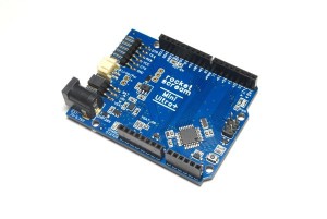
Cela fait longtemps que je cherche une carte Arduino qui consomme le minimum de courant pour pouvoir la mettre dehors sur batterie…. A force de chercher j’ai trouve une carte spécialement conçue dans cette optique : Rocket scream Mini Ultra +. La carte est disponible en ligne ICI.

dev00054-front

J’ai décidé de la tester avec un petit programme qui fait clignoter une led. Pour avoir un point de référence j’ai uploader le programme sur une arduino leonardo et sur la MiniUltra+.

20130508_100502

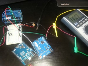
Voila la consommation des 2 cartes :

Arduino Leonardo : 48.4 mA
Rocket scream Mini Ultra + : 6.7 mA

La carte consomme 7 fois moins que l’Arduino Leonardo ! Je vais lui ajouter un module Xbee avec un mode sleep et refaire des mesures 😉

Update du 9 Mai :

Si on ajoute un module Xbee la consommation passe de 6.7 mA a 45 mA (ce qui correspond a la datasheet Xbee +40mA). J’ajoute aussi un capteur de lumière qui permettra au système domotique de savoir quand il faut fermer les volets ;). On a donc une consommation de 45 mA…..encore un peu trop a mon gout !

L’étape suivante est de faire dormir le module Xbee en utilisant la broche “DTR” du module. Il faut la mettre a l’état haut pour faire dormir le module et donc diminuer sa consommation (il faut aussi que le module soit configurer en sleep mode PIN). Je fais donc “dormir” le module 5 min puis ensuite l’Arduino allume le module et envoie la valeur de la luminosité. Voila le code :

//Libraries definitions
//Xbee library
#include 
//Deipara library
#include 

//pin guirlande led
const int _OutDebugLed = 8;
const int _OutXbeeWakeUp = 7;
const int _InLightPin = 4;

//Xbee objects
//create Xbee object to control a Xbee
XBee _Xbee = XBee(); 
//Create reusable response objects for responses we expect to handle
ZBRxResponse _ZbRxResp = ZBRxResponse(); 
//Global variable used in the program
int _CmdReceived = 0;
int _DataToSend = 0;

void setup()
{
  // start serial
  _Xbee.begin(XBEE_SPEED); 
  Serial.begin(XBEE_SPEED);
  //defined IO
  pinMode(_OutDebugLed, OUTPUT);
  pinMode(_OutXbeeWakeUp, OUTPUT);
  pinMode(_InLightPin, INPUT);

  digitalWrite(_OutDebugLed, LOW);

  delay(2000);
}

void loop()
{
  //digitalWrite(_OutDebugLed, HIGH);
  digitalWrite(_OutXbeeWakeUp, LOW);
  delay(5000);
  unsigned int val = analogRead(_InLightPin);    // read the input pin
  sendZigBeeMsg2(_Xbee,36,val,COORD_ADDR);
  //digitalWrite(_OutDebugLed, LOW);
  digitalWrite(_OutXbeeWakeUp, HIGH);
  delay(300000);

}

En utilisant ce code la consommation passe de 45 mA a 7mA (avec un petit pic a 30mA toutes les 5 minutes) ! Une dernière optimisation est de faire dormir le micro en plus du module Xbee. Je me suis inspire d’un article dispo ICI. Il s’agit d’utiliser le WatchDog pour réveiller le micro toutes les 8s (on ne peut pas faire plus) et attendre d’avoir fait ça pendant 5 minutes pour ensuite faire le vrai processus. Voila le code :

//Xbee library
#include <XBee.h>
//Deipara library
#include <Deipara.h>
// This library contains functions to set various low-power states for the ATmega328
#include <avr/sleep.h>

// This variable is made volatile because it is changed inside an interrupt function
// Keep track of how many sleep cycles have been completed.
volatile int sleep_count = 0; 
// 75 loop needed since ze sleep for 8s and want to wait 10 minutes
const int sleep_total = 75; 

//pin
const int _OutDebugLed = 8;
const int _InLightPin = 4;
const int _OutXbeeWakeUp = 7;

//Xbee objects
//create Xbee object to control a Xbee
XBee _Xbee = XBee(); 
//Create reusable response objects for responses we expect to handle
ZBRxResponse _ZbRxResp = ZBRxResponse(); 
//Global variable used in the program
int _CmdReceived = 0;
int _DataToSend = 0;

void goToSleep()   
{
  // The ATmega328 has five different sleep states.
  // See the ATmega 328 datasheet for more information.
  // SLEEP_MODE_IDLE -the least power savings 
  // SLEEP_MODE_ADC
  // SLEEP_MODE_PWR_SAVE
  // SLEEP_MODE_STANDBY
  // SLEEP_MODE_PWR_DOWN -the most power savings
  // I am using the deepest sleep mode from which a
  // watchdog timer interrupt can wake the ATMega328
  //digitalWrite(_OutDebugLed, HIGH);

  set_sleep_mode(SLEEP_MODE_PWR_DOWN); // Set sleep mode.
  sleep_enable(); // Enable sleep mode.
  sleep_mode(); // Enter sleep mode.
  // After waking from watchdog interrupt the code continues
  // to execute from this point.

  sleep_disable(); // Disable sleep mode after waking.
  //digitalWrite(_OutDebugLed, LOW);                   
}

void watchdogOn() 
{ 
  // Clear the reset flag, the WDRF bit (bit 3) of MCUSR.
  MCUSR = MCUSR & B11110111;

  // Set the WDCE bit (bit 4) and the WDE bit (bit 3) 
  // of WDTCSR. The WDCE bit must be set in order to 
  // change WDE or the watchdog prescalers. Setting the 
  // WDCE bit will allow updtaes to the prescalers and 
  // WDE for 4 clock cycles then it will be reset by 
  // hardware.
  WDTCSR = WDTCSR | B00011000; 

  // Set the watchdog timeout prescaler value to 1024 K 
  // which will yeild a time-out interval of about 8.0 s.
  WDTCSR = B00100001;

  // Enable the watchdog timer interupt.
  WDTCSR = WDTCSR | B01000000;
  MCUSR = MCUSR & B11110111;
}

ISR(WDT_vect)
{
  sleep_count ++; // keep track of how many sleep cycles have been completed.
}

void setup(void) 
{
  // start serial
  _Xbee.begin(XBEE_SPEED); 
  Serial.begin(XBEE_SPEED);
  watchdogOn(); // Turn on the watch dog timer.
  pinMode(_OutDebugLed, OUTPUT);
  pinMode(_OutXbeeWakeUp, OUTPUT);
  pinMode(_InLightPin, INPUT);
}

void loop(void) 
{
  goToSleep(); // ATmega328 goes to sleep for about 8 seconds and continues to execute code when it wakes up

  if (sleep_count == sleep_total) 
    {
    sleep_count = 0;
    // CODE TO BE EXECUTED PERIODICALLY
    //digitalWrite(_OutDebugLed, HIGH);
    digitalWrite(_OutXbeeWakeUp, LOW);
    delay(5000);
    unsigned int val = analogRead(_InLightPin);    // read the input pin
    sendZigBeeMsg2(_Xbee,36,val,COORD_ADDR);
    //digitalWrite(_OutDebugLed, LOW);
    digitalWrite(_OutXbeeWakeUp, HIGH);
  }
}

Avec cet toute derniere version le module (Micro + Xbee) se reveille toutes les 10 minutes pour recuperer la luminosite et l’envoyer au systeme domotique. La consomation finale du module complet est de 4.9mA pendant la veille !! On passe donc d’un montage V1 de 96mA (Arduino Uno + Xbee) a un nouveau module consomant 4.9mA (UltraMini+ et Xbee et sleep mode pour tous).

On a donc diviser la consommation du module par 20!!!!

Update du 17 Mai :

J’ai remarque que la batterie se decharge beaucoup plus vite que prevue….et apres quelques investigations le probleme vient du module Xbee qui ne repasse pas en mode sleep lorsque il est en dehors du reseau ZigBee. En googlant un peu j ai trouve un post similaire sur les forum DIGI (constructeur du Xbee) :

XBee S2 end device goes crazy when coordinator loses power

“The Xbee product manual states that when an end device loses contact with it’s parent, the end device will poll for the parent, and if no reply is received in three polls the unit will go into a search for network mode.

I find that with Xbee S2 modems (that came in several L/H/T sensors I purchased), when the coordinator inadvertently loses power the end device modem instead starts a rapid fire output of data requests (assumed to be polls) at approximately 5ms intervals for indeterminate amounts of time, a minimum of 30+ seconds. In some instances the polling appears to never stop. In some instances the polling finally stops and a beacon request is sent as a start to a network search.”

Dans mon cas il est possible que le module soit hors réseau pendant un moment (je coupe les modules quand je ne suis pas a la maison)…. Il s’agit d un bug qui est normalement corriger dans les derniers firmware (j ai pourtant mis a jour les modules mais le pb continue).

J’ai donc decider de ne plus utiliser le “sleep mode” des modules et de simplement les alimenter a la demande avec 2 broches de la platine Arduino. J’ai applique la meme methode a tous les autres capteurs de la platine (Temperature, Humidite, et luminosite). Il ne sont alimenter que toutes les X minutes pour effectuer les mesures et les envoyer a la centrale. Voila la derniere version du code :

//Xbee library
#include <XBee.h>
//Deipara library
#include <Deipara.h>
// This library contains functions to set various low-power states for the ATmega328
#include <avr/sleep.h>
//RHT03 library
#include <DHT22.h>

// This variable is made volatile because it is changed inside an interrupt function
// Keep track of how many sleep cycles have been completed.
volatile int sleep_count = 0; 
// 75 loop needed since ze sleep for 8s and want to wait 10 minutes
//const int sleep_total = 75; 
const int sleep_total = 60; 

//pin
const int _InPinDht22 = 6;
const int _OutPowerLightSensor = 7;
const int _OutXbeePower1 = 8;
const int _OutXbeePower2 = 9;
const int _OutPowerDHT22 = 10;
const int _InLightPin = 4;

//Xbee objects
//create Xbee object to control a Xbee
XBee _Xbee = XBee(); 
//Create reusable response objects for responses we expect to handle
ZBRxResponse _ZbRxResp = ZBRxResponse();
//Setup a DHT22 instance
DHT22 _Dht22(_InPinDht22); //Setup a DHT22 instance 
//Global variable used in the program
int _CmdReceived = 0;
int _DataToSend = 0;

void goToSleep()   
{
  // The ATmega328 has five different sleep states.
  // See the ATmega 328 datasheet for more information.
  // SLEEP_MODE_IDLE -the least power savings 
  // SLEEP_MODE_ADC
  // SLEEP_MODE_PWR_SAVE
  // SLEEP_MODE_STANDBY
  // SLEEP_MODE_PWR_DOWN -the most power savings
  // I am using the deepest sleep mode from which a
  // watchdog timer interrupt can wake the ATMega328
  //digitalWrite(_OutDebugLed, HIGH);

  set_sleep_mode(SLEEP_MODE_PWR_DOWN); // Set sleep mode.
  sleep_enable(); // Enable sleep mode.
  sleep_mode(); // Enter sleep mode.
  // After waking from watchdog interrupt the code continues
  // to execute from this point.

  sleep_disable(); // Disable sleep mode after waking.
  //digitalWrite(_OutDebugLed, LOW);                   
}

void watchdogOn() 
{ 
  // Clear the reset flag, the WDRF bit (bit 3) of MCUSR.
  MCUSR = MCUSR & B11110111;

  // Set the WDCE bit (bit 4) and the WDE bit (bit 3) 
  // of WDTCSR. The WDCE bit must be set in order to 
  // change WDE or the watchdog prescalers. Setting the 
  // WDCE bit will allow updtaes to the prescalers and 
  // WDE for 4 clock cycles then it will be reset by 
  // hardware.
  WDTCSR = WDTCSR | B00011000; 

  // Set the watchdog timeout prescaler value to 1024 K 
  // which will yeild a time-out interval of about 8.0 s.
  WDTCSR = B00100001;

  // Enable the watchdog timer interupt.
  WDTCSR = WDTCSR | B01000000;
  MCUSR = MCUSR & B11110111;
}

ISR(WDT_vect)
{
  sleep_count ++; // keep track of how many sleep cycles have been completed.
}

void setup(void) 
{
  pinMode(_OutPowerLightSensor, OUTPUT);
  pinMode(_OutPowerDHT22, OUTPUT);
  pinMode(_OutXbeePower1, OUTPUT);
  pinMode(_OutXbeePower2, OUTPUT);
  pinMode(_InLightPin, INPUT);

  digitalWrite(_OutPowerLightSensor, LOW);
  digitalWrite(_OutPowerDHT22, LOW);
  digitalWrite(_OutXbeePower1, LOW);
  digitalWrite(_OutXbeePower2, LOW);

  // start serial
  _Xbee.begin(XBEE_SPEED); 
  Serial.begin(XBEE_SPEED);

  delay(500);

  watchdogOn(); // Turn on the watch dog timer.
}

void loop(void) 
{
  goToSleep(); // ATmega328 goes to sleep for about 8 seconds and continues to execute code when it wakes up

  if (sleep_count > sleep_total) 
    {
    sleep_count = 0;
    //First we power the Xbee so it has time to reach the network and the other captor
    digitalWrite(_OutXbeePower1, HIGH);
    digitalWrite(_OutXbeePower2, HIGH);
    digitalWrite(_OutPowerDHT22, HIGH);
    digitalWrite(_OutPowerLightSensor, HIGH);
    //Then wait 0.5s to be ready 
    delay(1000);
    //we read the light sensor value
    unsigned int aLightValue = analogRead(_InLightPin);
    //we turn it off
    digitalWrite(_OutPowerLightSensor, LOW);
    delay(2000);
    //Then read T
    DHT22_ERROR_t errorCode;
    errorCode = _Dht22.readData();
    int aTempValue=_Dht22.getTemperatureCAsInt();
    int aHumidityValue=_Dht22.getHumidityAsInt();

    digitalWrite(_OutPowerDHT22, LOW);

    //we wait few second to be sure Xbee reach the network
    delay(3000);
    //we send the info
    sendZigBeeMsg2(_Xbee,36,aLightValue,COORD_ADDR);
    delay(50);
    sendZigBeeMsg2(_Xbee,37,aTempValue,COORD_ADDR);
    delay(50);
    sendZigBeeMsg2(_Xbee,38,aHumidityValue,COORD_ADDR);
    //we turn off the xbee module
    digitalWrite(_OutXbeePower1, LOW);
    digitalWrite(_OutXbeePower2, LOW);
  }
}

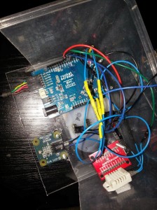
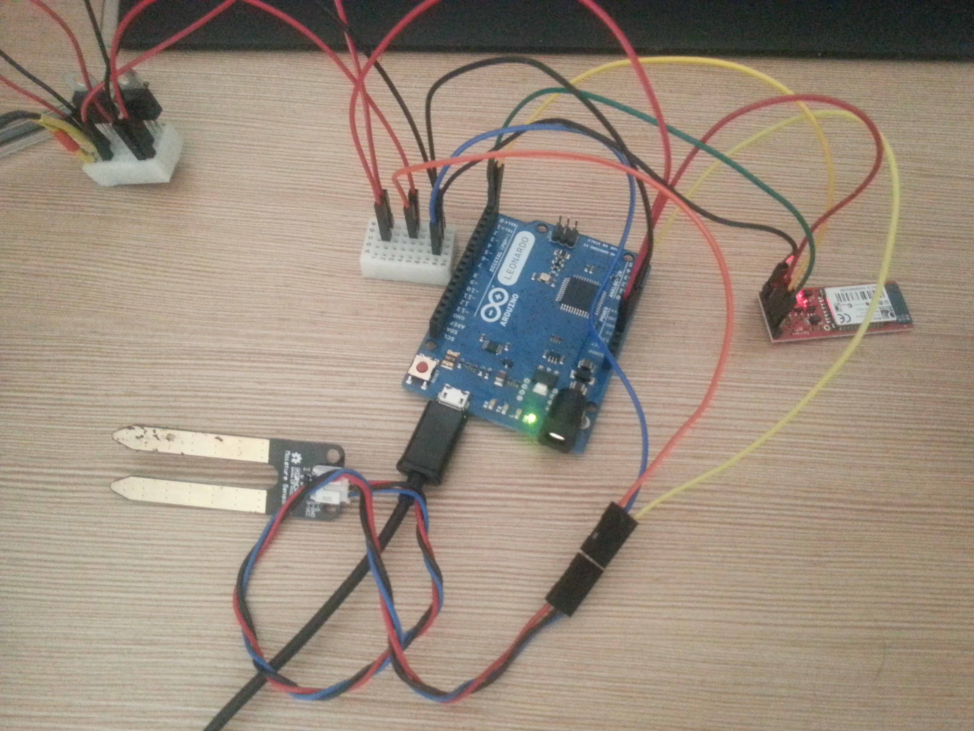
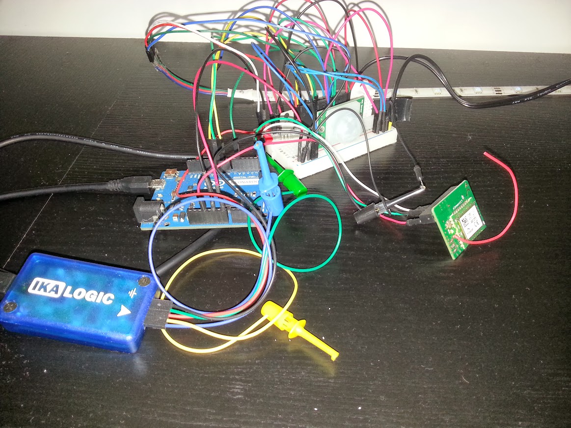
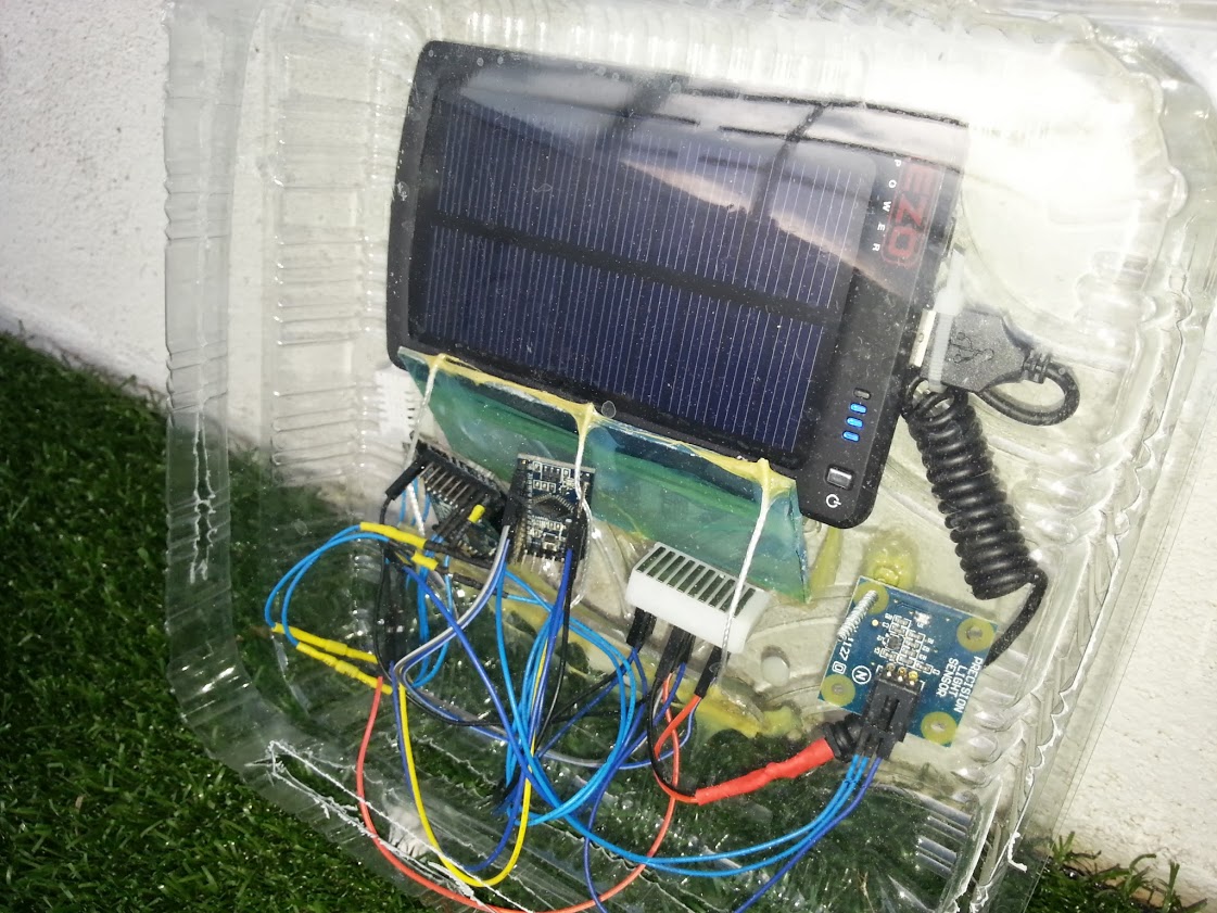
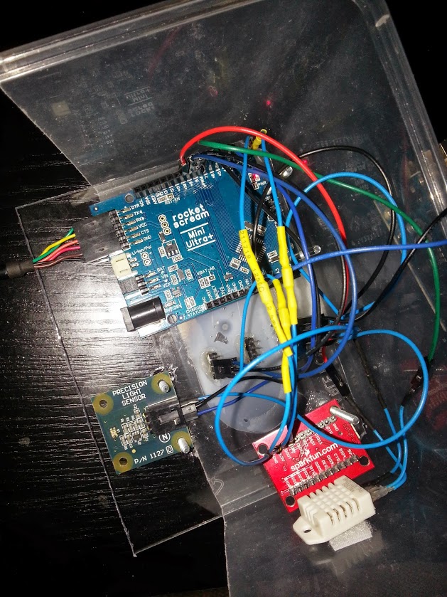
Grâce a ce nouveau code/design le module ne consomme que 1.6mA en veille et aux alentours de 40mA lorsqu’il se réveille pour effectuer les mesures toutes les X minutes (toutes les 9 minutes pour l instant). Voila une photo du montage final :

20130517_113148

Smart tableau – nouveau End Device pour mon system domotique

J’ai décidé d’ajouter un nouveau « end device » dans le système pour pouvoir mesure/contrôler certains éléments de la cuisine.

Cadre_avant

Les fonctions de ce nouveau « end device » sont :

  • Détection de personne (capteur PIR)
  • Détecteur de fumée (démontage d’un détecteur de fumée du commerce)
  • Mesure Température et humidité

L’ensemble des capteurs est monte à l’arrière d’un cadre qui est pose dans la cuisine au-dessus des rangements. Le capteur de fumée est donc très prêt du plafond pour être sur qu’il détectera bien un incendie.

L’ensemble du montage communique par ZigBee avec le coordinateur. Ensuite le coordinateur transmet les infos au « brain » au travers d’une liaison série USB (exactement comme les autres devices).

Le « brain » python doit donc maintenant être capable de comprendre ce nouveau device pour, par exemple, prévenir de la détection d’un incendie.

Ceci est très simple grâce au design du system domotique puisque le « détecteur incendie » correspond parfaitement à un device de type « interrupteur stable » et donc il suffit de rajouter dans le « brain » une nouvelle action pour cet interrupteur stable en particulier. On ajoute donc :

if ((aOneDevice.id == 2) and (aOneDevice.currentStatus=="unstable")):
 sendEmailFireDetected()

dans la boucle des détections évènements trigger par les interrupteurs stable :

#Step 1 : Verifier tous les detecteurs (interupteurs stables) pour voir si ils ont ete actives et prendre les actions correspondantes avant de les reset
        #Par exemple si le detecteur de fumee a ete active alors on va envoyer un mail 
        logging.info("Checking all possible event")
        for aOneDevice in iListOfDevice.registeredDevices:
            logging.debug("checking event : " + str(aOneDevice.id))
            if ((aOneDevice.id == 2) and (aOneDevice.currentStatus=="unstable")):
                sendEmailFireDetected()
            elif ((aOneDevice.id == 10) and (aOneDevice.currentStatus=="unstable")):
                self.PeopleDetectedEntree(iListOfDevice)
            elif ((aOneDevice.id == 9) and (aOneDevice.currentStatus=="unstable")):
                self.PeopleDetectedCharlesRoom(iListOfDevice)
            aOneDevice.reset()

Ensuite il ne reste plus qu’à créer la fonction « send fire detection » pour prévenir l’utilisateur qu’un incendie a été détecté. Pour le moment on se contente d’envoyer un email mais dans l’avenir on peut simplement faire évoluer cette action avec par exemple un appel automatique au pompier

L’envoie de l’email est assure par la fonction suivante :

def sendEmailFireDetected():
 '''Envoie email lors de la detection incendie'''
 logging.error("Envoi email detection incendie")
 # Define email addresses to use
 addr_to = Config["addr_to"]
 addr_from = Config["addr_from"]
 # Define SMTP email server details
 smtp_server = Config["smtp_server"]
 smtp_user = Config["smtp_user"]
 smtp_pass = Config["smtp_pass"]

 # Construct email
 expires = datetime.datetime.now()
 msg = MIMEText('Fire detected at ' + str(expires))
 msg['To'] = addr_to
 msg['From'] = addr_from
 msg['Subject'] = 'Fire alarm'

 # Send the message via an SMTP server
 s = smtplib.SMTP(smtp_server, 587)
 s.login(smtp_user,smtp_pass)
 s.sendmail(addr_from, addr_to, msg.as_string())
 s.quit()