Burn bootloader Arduino nano 33 BLE

Quick post to explain how to upload the original Arduino nano 33 BLE bootloader in case you erased it by mistake (another story for another post)…

Hardware

I have a J-Link EDU Mini as external programmer for the chip of the board (Nrf52840 – https://www.nordicsemi.com/Products/Low-power-short-range-wireless/nRF52840) It s a very cheap programmer (15$) that can only be used for non commercial application but offer the same functionality that a 400$ programmer. Thx Nordic for offering that to hobbyist ! More info about it here: https://www.segger.com/products/debug-probes/j-link/models/j-link-edu-mini/
I would also suggest to buy an adapter for it “designed to make it easier to use ARM dev boards that use slimmer 2×5 (0.05″/1.27mm pitch) SWD cables for programming” like this one: https://www.adafruit.com/product/2743

Connection

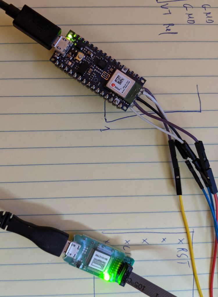
There are 5 cables to connect between the Arduino nano 33 BLE and the J-Link programmer but first let’s locate the Probe on the Nano 33 BLE (I used another nano 33 BLE sense board in pic but it is the same as the Nano 33 BLE).
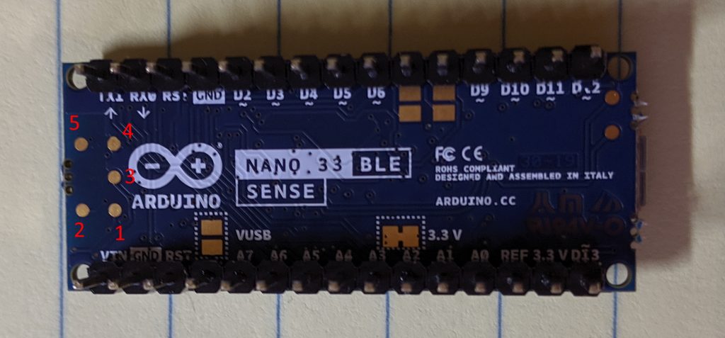
The pins are:
1 – Vref (3.3V in our case)
2 – SWDIO (data)
3 – SWCLK (clock)
4 – Ground
5 – Reset

The tricky part will be to solder the cable because all the points are small and close to each other (I wish they expose them with a more practical way but we are lucky to have access to them already;) )

The mapping of the J-Link is explain on the official doc https://www.segger.com/products/debug-probes/j-link/models/j-link-edu-mini/ and it s even better if you use the adapter since the name will be written of it
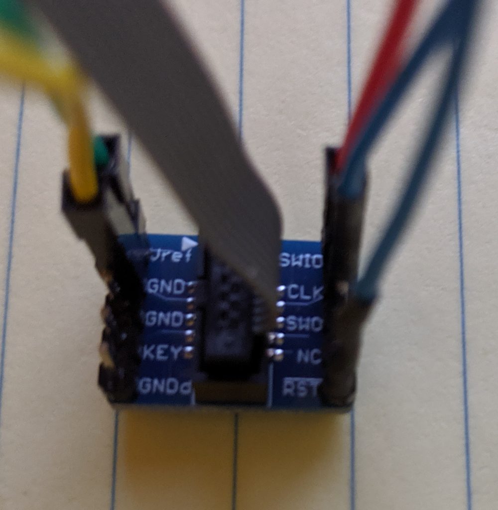
The mapping is thus

Nano 33 BLEJ-Link EDU
Vref Vref
SWDIOSWIO
SWCLKCLK
GroundGND (any)
ResetRST

Software

You need to full J-link package (which is free) that you can download on Nordic website here: https://www.segger.com/downloads/jlink/ We are going to use J-Flash lite to be specific but better install the whole package 😉

Turn on the 2 board (don t forget to plug tha nano 33 or Vref will be 0V and J-Link will fails to connect to the Arduino board).

We need to locate the Arduino Bootloader of the nano 33 BLE file that we are going to upload with J-Flash lite….. It is located here C:\Users\charl\AppData\Local\Arduino15\packages\arduino\hardware\mbed\1.1.2\bootloaders\nano33ble (of course you need to adapt) and contains 3 files

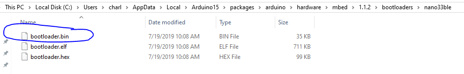
We are going to use the bin one (should works with hex one too) and give this path in J-Flasher. Be sure to choose nrf52840 in the list of device (the rest of parameters can stay with their default value) and then click “Program Device”.

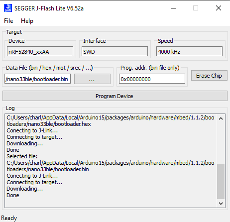
You should had some logs similar to these one and then the board should have back its original Arduino bootloader and should be usable again in the Arduino UI 😉

DEFCON scale

Let’s start with an explanation of what is the DEFCON scale from https://en.wikipedia.org/wiki/DEFCON:

The DEFCON system was developed by the Joint Chiefs of Staff (JCS) and unified and specified combatant commands.[2] It prescribes five graduated levels of readiness (or states of alert) for the U.S. military. It increases in severity from DEFCON 5 (least severe) to DEFCON 1 (most severe) to match varying military situations.

https://en.wikipedia.org/wiki/DEFCON

and a picture of the final result to better understand how it look like

Hardware

The scale is made in wood with 9 LEDs behind each level/number

The logic of the scale comes from an arduino Micro with a BLE sparkfun BLE module “SparkFun Bluetooth Mate Silver – https://www.sparkfun.com/products/12576 ” (which is not used for now). The Arduino is powered by 9V regulated from the 12V main power (used for LED). Each number back light is control by a MOSFET (P30N06LE) driven by the Arduino. There are also 2 buttons for tests to increase/decrease the level.

Software

Arduino

The arduino micro communicate with a computer using USB to receive the level it should set on the scale. It will do that buy driving 5 MOSFET to light the proper panel. It also listen to press on 2 buttons to raise/decrease the level (for test purpose). The code is quite simple.

PC

The scale communicate with a computer to receive its level it should set. The level is computed from my work company issue tracking tool. The computation part code interface with some of my company API and is thus not part of the code…. You will have to code your logic in the python code in the function “getSeverity” which should return an integer between 5 (low level) and 1 (critical level) as the DEFCON standard 😉

The python part should be put in a crontab to regularly update the scale 😉

More picture of the project HERE and the code is HERE.

Quick table with leftover 😉

I had some old generation Arduino (Uno) and LED strip (white – non addressable) that I no longer need so I decided to use them to do a nice table. 

One push button to change the PWN and thus lighting of the table and a LED stip plug with a MOSFET driven by the arduino. 

Here is the result 

More pic here:  https://photos.app.goo.gl/ny27bXQZDyYSCEhB9

Very simple quick code here: https://bitbucket.org/charly37/ledtable/src/master/

Just wanted to do a quick post before working on the post of next project which is more fun. 

AcTricker

Im working in an openspace of 15 peoples and most of us are very cold. There is one thermostat for the whole openspace with the actual temperature display on it but it seems we cannot change the desired temperature… We complain several times to our management about it and after some time the responsible of the amenities comes and explains us the situation. The temperature is set by the landlord for the whole building and the sensor in our openspace is just to detect the temperature in our space to open air vent or not. In other word…there is nothing they can do about it, is it? 

This is the AcTricker! The solution to our problem 😉

It’s design to be put against the wall around the temperature sensor. It will create a cold micro climate around the sensor to trick it thinking that the office is cold and thus never start the AC in our openspace. It works with a Peltier device that generate cold inside the enclosure and Hot outside of the enclosure when a current is passing (I did not research how/why it is work but just use it as is).

The Peltier device is in sandwich with the hot face facing outside with a big heatsink/fan to dissipate the heat and the cold side facing in the enclosure with a smaller heatsink/fan. It is important to dissipate the heat/cold quickly otherwise the Peltier become inefficient. It would had been enough to stop here and the device would had been functional nevertheless I wanted to add more functionalities… 

The whole system is control with an android application with Bluetooth so people can check what is the simulated temperature inside the enclosure and act on it by stopping the Peltier device and fans. The brain of the whole system on the device side is an Arduino micro (small size). It is connected to a Bluetooth modem and a temperature/humidity sensor (DHT22/RHT03) for data exchange. There is also 2 MOSFET to control the fans and 1 static relay to control the Peltier device. 

The android application allows to retrieve Temperature and Humidity and control the fans and Peltier. The application design is very similar to the one I created for previous project (like this one) and use the BT of android to communicate with the device so i will not details again here. The Arduino side is also very similar to previous projects (same one than the app). Here is the system after it is plug (android screen capture on the right and device on the left) :

and the result 10 minutes after:

We reduce the temperature from 23 degrees Celsius to 19 degrees Celsius leading the AC to completely stop 😉

Code is on my bitbucket repo.

Improvement idea: Have the Arduino automatically stopping the Peltier/fan when the temperature inside is low enough to save power and reduce noise. 

Static Relay ??

I used a static relay for the Peltier device after burning 2 MOSFETs when trying to control the Peltier with them. The MOSFET were becoming very hot very quick and even damage the breadboard as you can see on the picture

At the beginning, I was not sure why the MOSFET was becoming so hot. I know that the Peltier device use lot of current (around 7A) but the MOSFET I used (P16NF06FP) should had been OK since it was able to handle load up to 11A (I use the TO-220FP package which is plastic package and thus dissipate less heat than the metal package):

After some research (and particularly this blog post) I think the explanation is that the MOSFET was not able to handle 11A with my configuration. I was driving the MOSFET from the Arduino with a voltage of 5V but the MOSFET require more voltage to be fully open. I was thus not able to use the full MOSFET capability due to a gate voltage too low. The impact of the gate voltage (Vgs) on the possible current output (Id) is also in the datasheet:

As you can see if we switch the Gate voltage from 5V to the recommended 10V the current we can drain grow from 7A to more than 28A.

This is why the MOSFET was become too hot and unusable. I should have bought a MOSFET design to be driven with a gate voltage more compatible with Arduino like the IRL540.

Electric train hack proto

This will be a very quick post since there is nothing new on this project….except maybe the use of openscad to do the design of the train structure.

Original goal is to have a small electric train running all over the office hanging on the celling. This is the prototype 😉

Train_proto

I simply buy an electric train on Amazon :

http://www.amazon.com/Bachmann-Trains-Thoroughbred-Ready–Scale/dp/B001RG7LDU/ref=sr_1_12?s=toys-and-games&ie=UTF8&qid=1437179429&sr=1-12

Then I rip it apart to understand how it works to be able to hack it.

Train principle

The train itself is very very stupid and is just some metal structure (pretty heavy by the way) with a motor.

Train_rip

The power for the motor comes directly from the rail through the wheels:

Train_wheel

The rails on the other side are smarter since there is a control panel to change the train speed/direction.

Rail_train

The principle is thus very simple…..The command panel generate a different tension in the rail to increase/decrease the speed. It can also invert the tension to go revert.

Hack it

I wanted several things:

  • Possibiility to control the train from phone
  • Train should works without a close circuit (in the office we only have one straigt way).

I decided to put the logic in the train rather than the rail. To do so I used an Arduino Micro (same as leonardo but smaller) with a motor controller and a BT receiver. There is nothing new here that I already done/explain in previous project except the motor controller.

The Bluetooth communication with an Android APP is the same software that the one used in this previous project : http://djynet.net/?p=639

The motor controller is the one of Sparkfun (HERE) and can control up to 2 motors. I used it to be able to change the motor rotation direction and speed (with PWM from arduino). This is indeed mandatory because the train will have to go in the 2 directions due to the linear rail circuit (one strait line).

The rails have now a constant tension of 12V from a AC/DC converter which power all the cards. The train is equipped with 2 sensors at front and rear. They are used to detect collision at the end of rail road and change the motor direction to go reverse

collision_sensor

The program is pretty simple since it just monitor collision sensor to change direction and serial bus for incoming Bluetooth message.

Finally I needed to put all that on the top of the train base with a nice 3D printed support. This was the good opportunity to try 3D printing. I done the design with OpenScad

Thus it might be the application you are looking for when you are planning to create 3D models of machine parts but pretty sure is not what you are looking for when you are more interested in creating computer-animated movies.

OpenSCAD is not an interactive modeller. Instead it is something like a 3D-compiler that reads in a script file that describes the object and renders the 3D model from this script file.

To sum up….you code your design and then compile it to generate the STL file 😉

I just created a basic shape with the place for the sensor at both end and then upload it on shapeways (a cloud 3D printing service).

train_3d_base

It fit perfectly the train and here is the final result once everything is mounted on it:

train_final

All the code (Arduino, Android, OpenScad) is available on my bitbucket account here.

Next step…..why not a camera on the train streaming live 😉

Bluetooth Arduino for moisture sensor

This WE I wanted to try BT communication with an Arduino…. To have a real project I decided to use a moisture sensor to detect from my phone if my green plant needs some water.

Global1

Global2

Arduino Board

To do so I bought a sparkfun BT module “Bluetooth Mate Silver” available following this direct link : https://www.sparkfun.com/products/12576

The moisture sensor is pretty standard : http://www.dfrobot.com/index.php?route=product/product&product_id=599#.U8JDQbE39b0

The connection to the BT module is pretty easy with Power (+3.3V, Gnd) and serial Data (Rx BT – Tx Leonardo and Tx BT – Rx Leonardo). As soon as the BT module is powered up it will be visible as a BT module.

2014-07-12-09-38-59

On the Arduino side I done a very simple program which will listen on the serial link established with the BT module. Once the Leonardo received a char ‘h’ it will read the humidity sensor value (analog read) and send it back on the BT link. Here is the code :

/*
Created by Charles Walker (charles.walker.37@gmail.com)
 Test program for bluetooth communication
 Tested with Arduino Leonardo and BT module Mate Silver (sparkfun)
 */

void setup()
{
  //USB Serial port
  Serial.begin(115200);
  //BT module serial port
  Serial1.begin(115200); 
}

void loop()
{
  delay(5000);
  if(Serial1.available())  
  {
    //We received something on BT module
    char aReceived;
    aReceived = (char)Serial1.read();
    Serial.print("Receveid from BT module :");
    Serial.println(aReceived);  

    // if we received a read humidity request
    if (aReceived=='h')
    {
      // Reading humidity
      unsigned int aHumidityValue;
      aHumidityValue=analogRead(0);
      Serial.print("Moisture Sensor Value:");
      Serial.println(aHumidityValue);
      // Sending it to the BT module
      Serial1.println(aHumidityValue);
    }
  }
  if(Serial.available())  
  {
    //We received something on USB serial line - We will send it to the BT module
    char aToBeSend;
    aToBeSend = (char)Serial.read();
    Serial.print("Going to send :");
    Serial.println(aToBeSend);

    //Sending it to the BT module
    Serial1.print(aToBeSend);
  }
}

The last version is available on bitbucket HERE.

The second part is the Android application which will be able to interact with the Arduino module through BT communication. Before starting coding it I wanted to verify that the Arduino part is working fine.

To do so I download a Arduino App able to communicate over BT. I tried few of them and the best one I find is :

https://play.google.com/store/apps/details?id=ptah.apps.bluetoothterminal

I installed it and then try sending some commands to the Leonardo board.

BT_Moisture_Test

The application properly connects to the BT module and then we are able to send some commands. The Leonardo only respond to the ‘h’ command which trig moisture read and send it back to the phone.

Android application

First step….. Fix android Studio Beta 0.8 issue….. See : http://djynet.net/?p=652
Android APP creation in a dedicated thread….. See : http://djynet.net/?p=658

Conclusion :

The results with the sensor in moist earth (or not) with the Arduino and Android output.

Moisture_Ardu

Andro_Moisture

The whole code for the project (Android and Arduino) is on my bitbucket account here.

EnOcean library example

Following my last article on EnOcean library for Arduino I received some email because the usage example was not good. Indeed I probably didn’t copy past the last version of code so I decided to do a new example (and also improve the library).

This time I will command 1 LED strip using an EnOcean button PTM210. A short click on the button will change the LED strip color to a random one. A long click (more than 2s) turns it off.

Here is the result:

The system requires a strip RGB led, an Arduino Leonardo, an EnOcean TCM 310 receiver and an EnOcean PTM210 emitter (button).

A made few modifications to my first EnOcean library by adding a new variable to check if a message were received on the TCM310. I also add a method to clean the “message” object. The EnOcean library is still available on my bitbucket repo (HERE)

The code is pretty simple. On each loop we check if a new message is available on the TCM310.

void loop() 
{
  delay(50); 
  _Msg.decode();
  if (_Msg.dataAvailable() == true)
  {
    actionTaker();
    _Msg.reset();
  }
}

If yes we will either start a timer if it is a button press or take an action if it is a button release. The action depend if the timer is finish or not (to determine if it is a long or short click).

void actionTaker()
{
  if (_Msg.getPayload() == 0x70)
  {
    Serial.println("The user push the button. Nothing to do appart starting the timer");
    _TimerExpire = false;
    MsTimer2::start(); // active Timer 2 
  }
  else if (_Msg.getPayload() == 0x00)
  {
    Serial.println("The user stop pushing the enocean button");
    if (_TimerExpire == true)
    {
      Serial.println("The user push was more than the timer (long push)");
      TurnOffLed();
      _NbClick=0;
    }
    else
    {
      Serial.println("The user push was quick (short push)");
      RandomLedColor();
      _NbClick=0;
    }
  }
  else
  {
    Serial.print("Received an unsupported command : ");
    Serial.println(_Msg.getPayload());
  }
}

There is also some extra function to determine a rand color and send it to the LED. The whole code is available on bitbucket (HERE)

Librarie EnOcean pour TCM 310 sur Arduino

Suite a mon article sur le décodeur EnOcean j’ai décidé de créer une libraire pour Arduino pour le TCM310.

Le code est extrêmement simple avec une classe “EnOcean” reprenant les éléments de la trame envoyé par le TCM310.

EnOceanMsg::EnOceanMsg()
{
  _dataLength1 = 0;
  _dataLength2 = 0;
  _optLength = 0;
  _packetType = 0;
  _headerCrc8 = 0;
  _org = 0;
  _payload = 0;
  _senderId1 = 0;
  _senderId2 = 0;
  _senderId3 = 0;
  _senderId4 = 0;
}

Cette classe possède une méthode “decode” qui utilise la lib software de l’arduino pour décoder ce qui arrive sur l USART :

void EnOceanMsg::decode()
{
while(Serial1.available() > 0)
{
    //Serial.println("Decoding");
    uint8_t aChar = Serial1.read();
    switch(_pos) 
    {
        case 0:
        if (aChar == START_BYTE) 
        {
            _pos++;
            //Serial.println("START");
        }
        break;

        case 1:
        // length msb
        _dataLength1=aChar;
        _pos++;
        //Serial.print("length msb:");
        //Serial.println(_dataLength1, HEX);
        break;
...

La classe offre également une méthode “pretty print” pour afficher ses éléments (et donc les informations reçu du TCM 310) :

void EnOceanMsg::prettyPrint()
{
Serial.println("Pretty print start");

Serial.print("length:");
char buf1[9];
sprintf(buf1, "%04x", getPacketLength());
Serial.println(buf1);
//Serial.println(getPacketLength());

Serial.print("Optional length:");
Serial.println(_optLength);

Serial.print("Packet type:0x");
Serial.println(_packetType, HEX);

La dernière version du code de la librairie est disponible sur BitBucket :
https://bitbucket.org/charly37/arduino_enocean_lib

Voila un exemple d’utilisation de la lib avec mon interrupteur EnOcean :

#include 

EnOceanMsg aMsg;

void setup()
{
  //USB
  Serial.begin(9600);
  //Pin 0/1
  Serial1.begin(57600);
}

void loop()
{
  delay(500); 
  aMsg.decode();
  Serial.println("Working");
  if (aMsg.getPayload() == 0x50)
  {
    Serial.println("OKOK");
  }
}

Ce qui produira le résultat suivant sur le moniteur série :

Working
Working
Pretty print start
length:0007
Optional length:7
Packet type:0x1
ORG:0xF6
Payload:0x70
Sender Id:8ba977
Pretty print end
Working
Pretty print start
length:0007
Optional length:7
Packet type:0x1
ORG:0xF6
Payload:0x0
Sender Id:8ba977
Pretty print end
Working
Working

Capteur meteo terrasse

Création d’un nouveau “end device” pour la terrasse :
20130602_203639

Il est base sur une carte Arduino non officielle : Ultra mini dont j ai déjà parle lors d article précédant. C’est la seule carte arduino que je connais qui est designe pour consommer le moins de courant possible (Cf article précédant) !

La carte consomme moins de 1mA en veille (et monte a 30 environ) lorsqu’elle passe a l état actif pour récupérer la température, humidité, et luminosité. Les données sont ensuite envoyées au système. Grâce a ces nouvelles data j’ai pu supprimer la “crontab” des volets qui ete fixe a 21h00. Maintenant les volets se ferme quand la luminosité extérieur est trop faible 😉

Le plus difficile a été de réduire la consommation de la carte (96mA a l origine avec une carte Arduino Leonardo) a un niveau acceptable pour que le chargeur solaire soit suffisant (1mA en veille et 30mA en émission pendant 5s toutes les 10 minutes). Tout les optimes pour la consomation de courant sont déjà explique dans mon article sur la carte “Mini Ultra +”.